78 AO2000-LS25 LASER ANALYZERS | OI/AO2000-LS25-EN REV. D
… 13 Maintenance
… Calibration of the device
Performing the calibration
Risk of injury due to process conditions.
The process conditions, for example high pressures and
temperatures, toxic and aggressive measuring media, can
give rise to hazards when working on the device.
• Before working on the device, make sure that the process
conditions do not pose any hazards.
• Shut off process connections and seal them with gas-tight
end caps to prevent the measuring medium escaping.
• Depressurize and empty the device / piping, allow to cool
and purge if necessary.
• If necessary, wear suited personal protective equipment
when working on the device.
Risk of suffocation
Risk of suffocation due to escaping purging gas when using
inert purging gases e.g. nitrogen (N
2
).
• Before opening the housing or flanged connections,
switch off the housing purging.
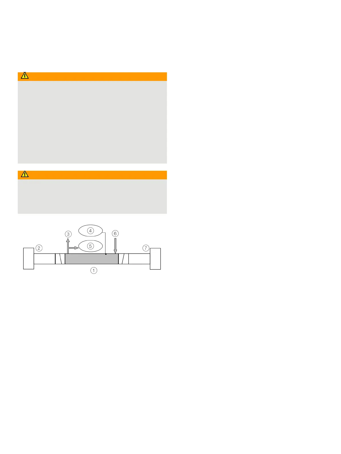
Calibration cell
Receiver unit
Gas outlet
Temperature sensor
Pressure sensor
Gas inlet
Transmitter unit
Figure 47: Calibration set
Perform the following steps to verify and calibrate:
1. Remove the transmitter and receiver units at the
measuring point.
2. Install the transmitter and receiver units on the test cell,
see Figure 47.
– Check the calibration set for leak tightness.e.g. by
testing with slight overpressure.
3. Connect the calibration cell temperature and pressure
sensors to the AO2000-LS25, see Connecting analog
inputs (option) on page 45.
4. Switch on the device, the device must be operational for
at least 1 hour before performing the verification and/or
calibration.
5. Start the service program, see Software start-up on
page 52.
6. Make sure that the measurement configuration
parameters are set correctly, see Measurement
configuration <Measurement configuration> on page 57.
– The flange length or concentration should be set to
zero.
– Check that the manually set temperature and
pressure are correct, or that the PLC inputs for the
gas temperature and pressure are correct.
7. Pressurize the cell with the calibration gas and set a
constant flow rate of 5 to 7 l/min.
– Wait until the system reaches stable levels.
8. Check if the reading is in agreement with the
concentration of the certified gas.
– Perform a PROPORTIONAL or GLOBAL calibration if
necessary, see Calibrating the device <Calibrate
instrument> on page 63 and PROPORTIONAL and
GLOBAL calibration on page 79.
9. Save the device settings to a file, see File download /
upload <File download / upload> on page 65.
10. Adjust the optical path parameters, pressure and
temperature again according to the measuring point
process parameters, see Measurement configuration
<Measurement configuration> on page 57.
11. Reinstall and commission the transmitter and receiver
units at the measuring point.

 Loading...


