AO2000-LS25 LASER ANALYZERS | OI/AO2000-LS25-EN REV. D 35
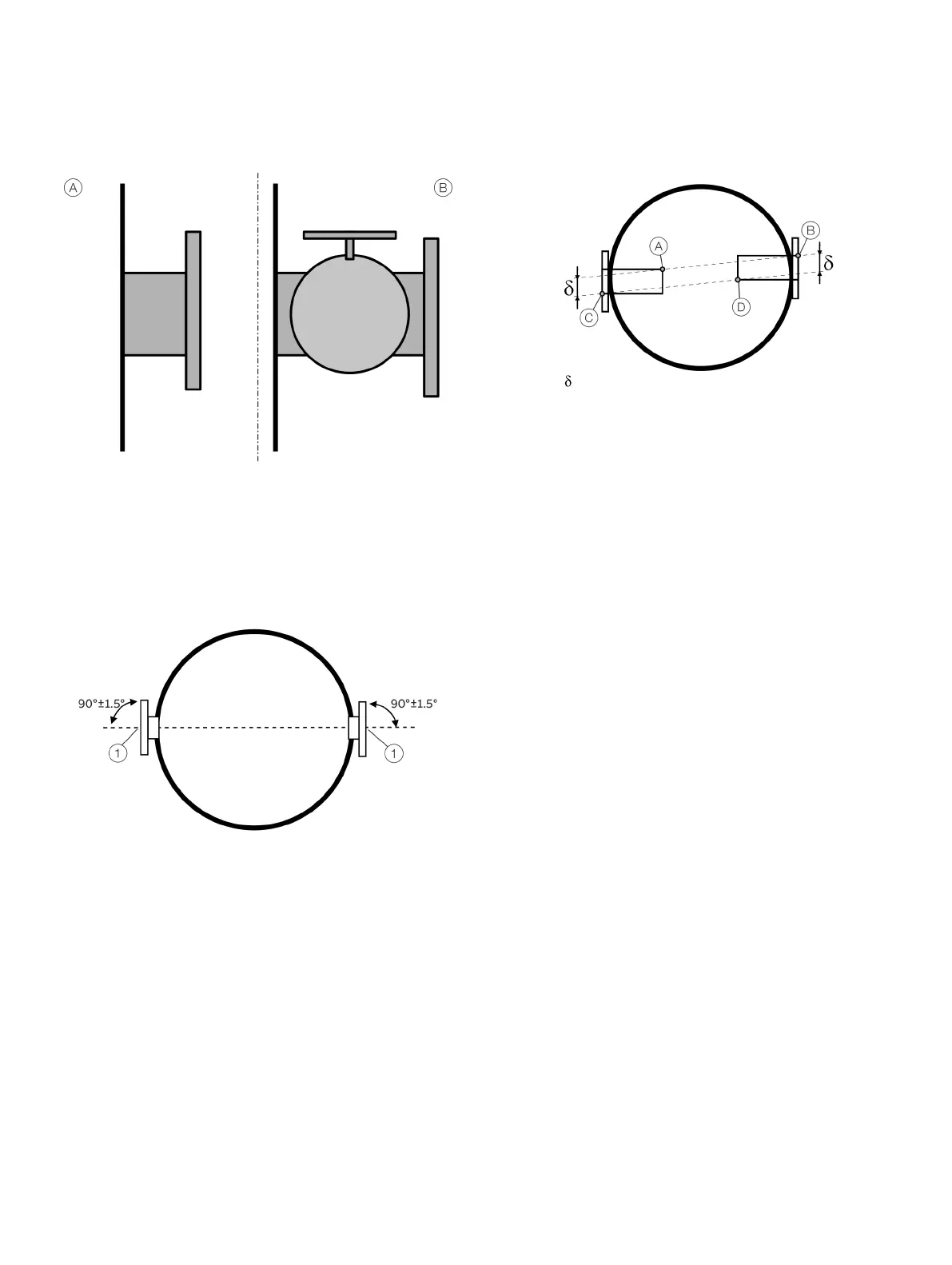
Flange without valve
Flange with valve
Figure 17: Flanges with and without valve
The analyzer is designed with an adjustment mechanism that
can tilt the flanges. The flanges welded to the stack should,
however, initially fulfil the specifications given in Figure 18 and
Figure 19.
Flange center
Figure 18: Flange angle alignment tolerances
The flange line-up should initially be better than 1.5° as specified
in Figure 18. The distance between the thought parallel lines
A–
B
und C–D (Figure 19) should fulfill the specifications in the
table to ensure that the tubes do not shield the laser beam.
Figure 19: Flange line-up tolerances
After correct adjustment and line-up of the device the maximum
allowed drift in angle between laser beam and receiver unit
center axis due to temperature effects or vibration, is ±0.3°
without having effect on the measurements.
Necessary tools and other equipment
The following equipment is necessary to install and calibrate the
equipment:
• 2 × open-end spanners for M16 bolts
• 1 × Allen key 5 mm for the locking screws on flanges
• 1 × PC (Windows 7® or higher) for installation and
calibration
• 1 × flat-bladed screwdriver 2.5 mm for electrical
connections

 Loading...


