4.4 POINT DISPLAYS 7 AND 8 - TWO LOOP DISPLAYS
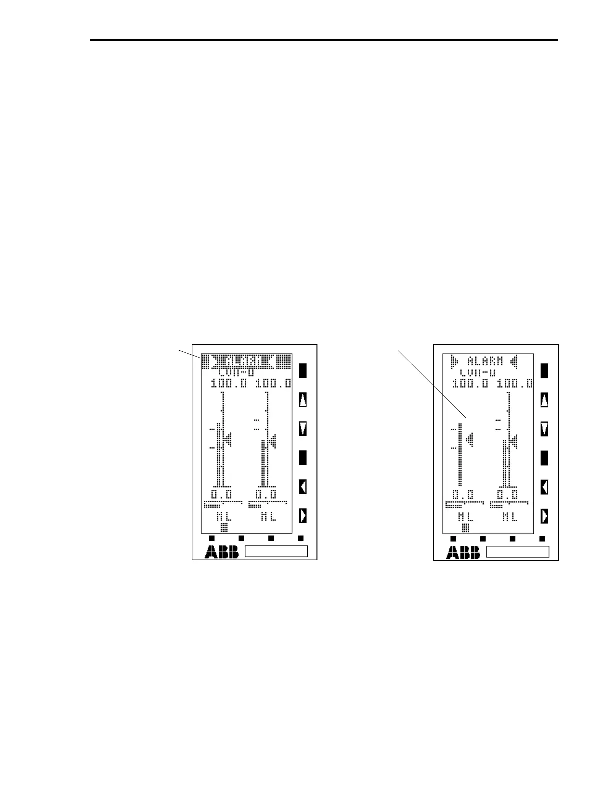
As shown in Figure 4-9, a Two Loop Display has two abbreviated Single Loop bar graph sets without
the digital information. Typical alarm indications are shown first on sheet 1of the figure, followed by
the displays with item call-outs on sheet 2. Each bar graph set represents an individual PID
controller (CON module). Two control module tag names appear at the top of the display. The tag
name for the right bar graph set is on the first line and the tag name for the left bar graph set is on
the second line. A bar graph set has a fifty segment vertical axis that has a 2% resolution. Upper
and lower range numeric values appear above and below the vertical axis. Left of the vertical axis is
the process variable bar. Alarm limit indicators are left of the process variable bar to indicate the
alarm limit values. On the immediate right of the vertical axis is the setpoint arrowhead. Beneath the
vertical axis is a sixteen segment horizontal axis that has a 6% (approximate) resolution. The output
bar moves under the horizontal axis. Beneath the output bar are the setpoint source and status
indicators (see Table 4-3). (A pending enable condition for either of these indicators causes it to
blink.) At the bottom of the Two Loop Display is the selection indicator block. The selection block is
toggled back and forth under either CON module bar graph with the F3 push button. It indicates
which bar graph set can be manipulated with the keypad push buttons. If the left or right process
variable bar moves beyond one of its alarm limit indicators, the vertical axis starts flashing on and off
to identify the out-of-tolerance CON module.
Figure 4-9. Two Loop Point Displays 7 and 8 (Sheet 1 of 2)
HORN OVERLAY -
(CONTENTS OF
A009 ARE
’wALARMx’, L065 =
1, AND L063 = 0
TO ALLOW CON-
TENTS OF A009
TO BE SUPERIM-
POSED OVER DIS-
PLAY. IF ’ALARM’
IS ENTERED IN
A009 WITHOUT
THE ’w’ AND ’x’,
THEN BRACKET
POINTS DO NOT
APPEAR IN OVER-
LAY.)
FLASHING
VERTICAL AXIS
(SHOWN OFF)
IDENTIFIES
CON-0 MODULE.
(THE PV BAR HAS
MOVED ABOVE
THE HIGH ALARM
INDICATOR. CON-
1 IS SET FOR
HIGH, HI-HI
ALARMS AND IS
THEREFORE
WITHIN TOLER-
ANCE.)
NOTE: ALL ALARMS SHOWN IN THIS FIGURE ARE FOR ILLUSTRATIVE PURPOSES ONLY AND
DO NOT REPRESENT REQUIRED SETTINGS FOR THE DIFFERENT CON MODULES.
CON-0 IS SET FOR HIGH/LOW (B335 = 0), CON-1 IS SET FOR HIGH/HI-HI (B340 = 4),
CON-2 IS SET FOR LOW/LO-LO (B345 = 5), AND CON-3 IS SET FOR HIGH/LOW SETPOINT
DEVIATION (B350 = 6).
Section 4. Operator Displays
4-21
 Loading...