4.10 POINT DISPLAY 32 - FOUR LOOP DISPLAY
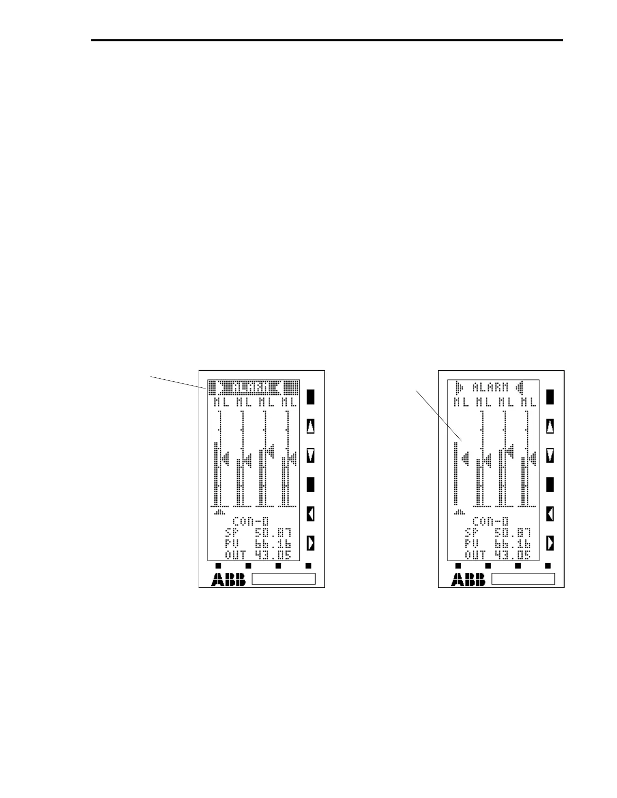
The Four Loop Display is illustrated in Figure 4-15. A typical alarm indication is shown on sheet 1
of the illustration, followed by the display with item call-outs on sheet 2. The Four Loop Display
has four abbreviated single bar graphs that appear simultaneously. Each bar graph represents an
individual PID controller (CON module). A bar graph has a fifty segment vertical axis. Left of the
vertical axis is the process variable bar. On the right side of the vertical axis is the setpoint arrow-
head. The top line of the display has the unit tag name. Immediately beneath the unit tag name
and above each vertical axis are the status indicators (e.g., M, A, R, and L, etc.). There is a selec-
tion pointer that appears below the bar graph bases and it is toggled from one bar graph to another
with the F3 push button. The selection pointer indicates which bar graph can be manipulated with
the keypad push buttons. Also, values in the four legend lines below the selection pointer change
to reflect conditions of the selected bar graph loop. The four legends are
CON-X
, where
X = 0-3
,
SP
for the setpoint value,
PV
for the process variable value, and
OUT
for the output value. If any
of the process variable bars move beyond its configured alarm limits, its vertical axis starts flashing
to identify the CON module with the alarm condition. If the horn overlay is configured (e.g., A009 =
’wALARMx’ or some suitable message, L065 = 1, and L063 = 0), then it blinks in reverse video.
The configured alarm limits do not appear as alarm indicators on each bar graph. All of the push
buttons are active for the Four Loop Display.
Figure 4-15. Point Display 32 - Four Loop Display (Sheet 1 of 2)
HORN
OVERLAY
(A009 =
’wALARMx’,
L065 = 1, AND
L063 = 0)
FLASHING
VERTICAL AXIS
(SHOWN OFF)
IDENTIFIES
CON-0 MODULE
Section 4. Operator Displays
4-31
 Loading...