2.7.2 SEPARATE 24 V DC POWER SOURCES TO CONTROLLER AND ITBs
The procedure to connect the controller TB2 screw lugs to a controller-dedicated 24 V dc power
source is provided in Table 2-4. The ITB power source must be negatively grounded; the controller
power source can float, be positively grounded, or negatively grounded.
Table 2-4. Controller-Dedicated 24 V dc Power Source
Step Procedure See Figure
1 From the negative distribution strip, connect the negative (-) 24 V input line,
via a remote SPST switch (SPST switch is on this input if positive ground),
to TB2-3 (
L2
).
Figure 2-15
2 From the positive distribution strip, connect the positive (+) 24 V input line,
via a remote SPST switch (SPST switch is on this input if negative ground or
if power supply floats), to TB2-4 (
L1
).
Figure 2-15
3 Connect TB2-1, Power Common (
PC
), to a common bus bar that is
connected to earth ground.
Individual wires should connect each controller Power Common (
PC
) screw
lug to the common bus bar.
Figure 2-15
Figure 2-16
4 Connect the earth ground to TB2-5, Chassis Safety Ground (
G
). Figure 2-15
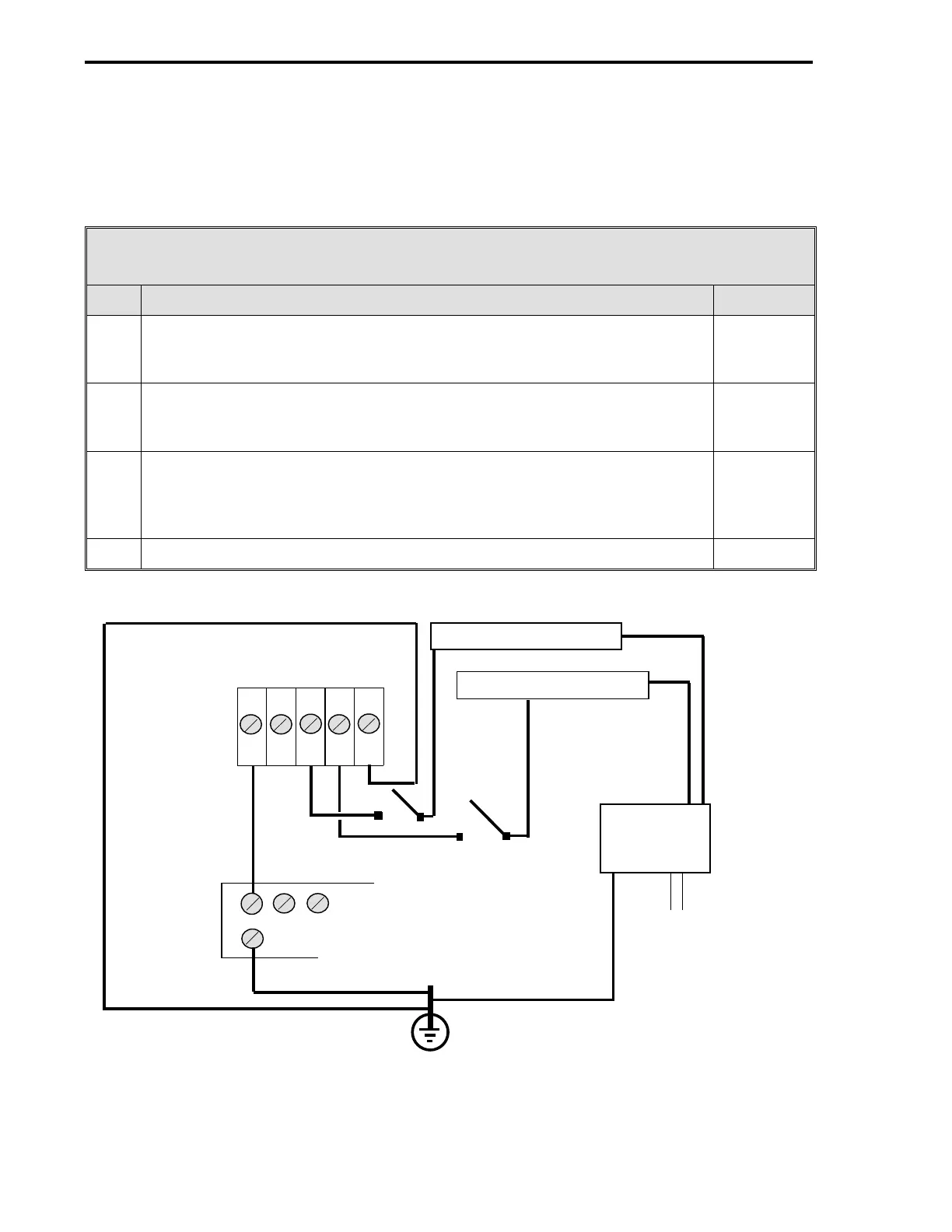
Figure 2-15. Controller Dedicated 24 V dc Power Source
1 2 3 4 5
PC L3 L2 L1 G
ONLY ONE SPST SWITCH NEEDED ON
P/S HOT SIDE (UNGROUNDED)
24 V dc
POWER
SUPPLY
-+
EARTH GROUND
TB2 (REAR OF
CONTROLLER)
AC
COMMON BUS BAR
NEG DIST STRIP
POS DIST STRIP
53MC5000 Process Control Station
2-20
 Loading...