2-13
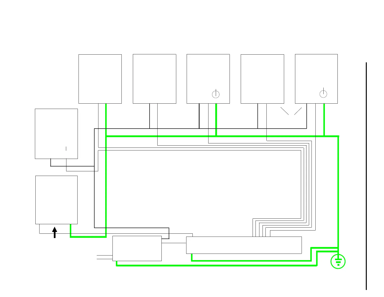
Figure 2-11. Power Connections Overview
Section 2. Installation
24 V DC P/S
COMMON BUS BAR FOR ALL CONTROLLERS
(NOT PROVIDED BY ABB AUTOMATION)
53MC5000
CONTROLLER†
SCADA
ADAPTER
BOARD
CORD SET
ITB
DUAL RELAY
ITB
ANALOG
ITB*
16 DIGITAL
INPUT/DIGITAL
OUTPUT ITB
(16DI/DO)**
6 DIGITAL
INPUT/4
DIGITAL
OUTPUT ITB
(6DI/4DO)***
TB2
PC L3 L2 L1
G
TB1
+24 V
▼
TB2
9 10
TB1
1 2
TB2
1 2
TB2
+ -
▼
1 2 3
TB3
+ -
▼
1 2 3
ac
OR
••••• *EITHER ANALOG ITB OR HART ITB. (BOTH CANNOT COEXIST.)
**EITHER 16DI/DO ITB OR HART MODEM ITB. (BOTH CANNOT
COEXIST.) ALSO, ASSUMES 24 V MODULES INSTALLED ON THE 16DI/DO
ITB.
***EITHER 6DI/4DO ITB OR HART MODEM ITB. (BOTH CANNOT
COEXIST.) ALSO, TB3-3 IS ALWAYS CONNECTED (CHASSIS SAFETY
•GROUND). TB3-1&2 CONNECTED ONLY FOR CCIs THAT REQUIRE
•POWER.
†••A 24 V DC DISTRIBUTION TERMINAL STRIP IS PREFERRED TO DAISY
CHAINED SINGLE WIRE DROPS.
+
-
SEE †
ABOVE
110/120 V ac,
220/240 V ac, OR
+24 V dc POWER
TO CONTROLLER
 Loading...