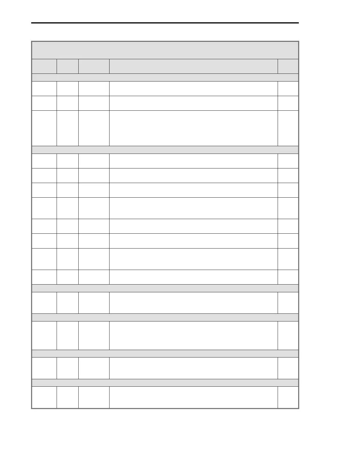
Table 7-3. CS2 Analog Backup Controller Datapoints
Data-
point Table Module Title and Function
De-
fault
AO0 - Backup Control Output (Cont)
C109 5-9 CON0 Output High Limit - Sets maximum Control Output signal
value in engineering units.
100
C110 5-9 CON0 Output Low Limit - Sets minimum Control Output signal value
in engineering units.
0
C118 5-9 CON0 Output Slew Rate - It is a rate limit applied to the output
value. When configured to a non-zero value, the output from
the Auto-Selector is only allowed to change by this amount
each scan time. A zero disables output slewing. It does not
affect manual operation.
0
CON0 Control Related Datapoints
C106 5-9 CON0 Proportional Band - Is the percent of error required to move
the output full scale for proportional action.
100
C107 5-9 CON0 Reset Time - Is the number of minutes per repeat of integral
action. It is mutually exclusive with Manual Reset.
0
C108 5-9 CON0 Rate Time - Represents the minutes proportional action is
advanced.
0
C111 5-9 CON0 Manual Reset - It determines output valve position when the
controller is in Auto and the error = 0. It is mutually
exclusive with Reset Time.
50
L106 5-9 CON0 Reverse Switch - 0 = Control Output
↑
if PV
↑
; 1 = Control
Output
↓
if PV
↑
.
1
L114 5-9 CON0 Auto Enable - Controller output is from the PID algorithm
when set to 1 and A/M push button is in Auto.
1
C115 5-9 CON0 Controller Span - Enter a value, that when added to the
Controller Lower Range value, will produce the control upper
range value in engineering units.
100
C116 5-9 CON0 Controller Lower Range - Enter a value that represents in
engineering units the control lower range value.
0
AO1 - Computer Control Status
L473 5-5 AO1 0-20 mA Output - 20 mA indicates computer control; 4 mA
indicates 53MC5000 control.
0
DI0 - Computer Ready
L264 5-6 DI0 Contact Input Invert - Normally, Computer Ready is enabled
if DI0 is closed. Set to 1 to reverse the required DI0
condition (DI0 open = Computer Ready) so that the computer
can drive the final element.
0
DI1 - Auto Enable
L265 5-6 DI1 Contact Input Invert - Normally, Auto Enable is permitted if
DI0 is closed. Set to 1 to reverse the DI1 condition required
to permit Auto Enable (DI1 open = Auto Enable).
0
DO0 - Computer Output Diverter
L024 5-7 DO0 When open, the computer output path is through the diverter
circuit diode to the final element. It is always in an opposite
state from DO1. (Not configurable.)
0
2 of 3
53MC5000 Process Control Station
7-6
 Loading...