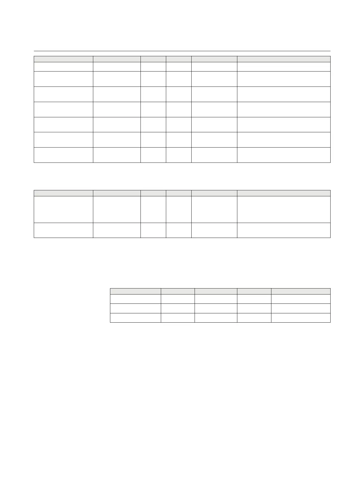
Name Values (Range) Unit Step Default Description
tIReset2 0.000 - 60.000 s 0.001 0.025 Time delay in IDMT reset (s), step 2
ACrv2 0.005 - 200.000 - 0.001 1.000 Parameter A for customer programmable
curve for step 2
BCrv2 0.50 - 100.00 - 0.01 1.00 Parameter B for customer programmable
curve for step 2
CCrv2 0.0 - 1.0 - 0.1 0.0 Parameter C for customer
programmable curve for step 2
DCrv2 0.000 - 60.000 - 0.001 0.000 Parameter D for customer
programmable curve for step 2
PCrv2 0.000 - 3.000 - 0.001 1.000 Parameter P for customer programmable
curve for step 2
CrvSat2 0 - 100 % 1 0 Tuning param for prog. under voltage
IDMT curve, step 2
Table 144: UV2PTUV Non group settings (basic)
Name Values (Range) Unit Step Default Description
ConnType PhN DFT
PhPh RMS
PhN RMS
PhPh DFT
-
- PhN DFT Group selector for connection type
GlobalBaseSel 1 - 12 - 1 1 Selection of one of the Global Base
Value groups
8.1.6 Monitored data
PID-3586-MONITOREDDATA v6
Table 145: UV2PTUV Monitored data
Name
Type Values (Range) Unit Description
UL1 REAL - kV Voltage in phase L1
UL2 REAL - kV Voltage in phase L2
UL3 REAL - kV Voltage in phase L3
8.1.7 Operation principle
M15326-3 v9
Two-step undervoltage protection (UV2PTUV) is used to detect low power system
voltage. If one, two or three phase voltages decrease below the set value, a
corresponding START signal is generated. The parameters OpMode1 and
OpMode2 influence the requirements to activate the START outputs: the measured
voltages 1 out of 3, 2 out of 3, or 3 out of 3 have to be lower than the corresponding
set point to issue the corresponding START signal.
UV2PTUV has two voltage-measuring steps with separate time delays. If the
voltage remains below the set value for the chosen time delay, the corresponding
trip signal is issued. To avoid an unwanted trip due to the disconnection of the
related high-voltage equipment, a voltage-controlled blocking of the function is
1MRK 506 382-UEN A Section 8
Voltage protection
Line distance protection REL650 2.2 IEC 263
Technical manual

 Loading...


