in, self-regulated DC/DC converter that provides full isolation between the
terminal and the external battery system.
The DC input is protected against inverse polarity within the rated DC voltage
range.
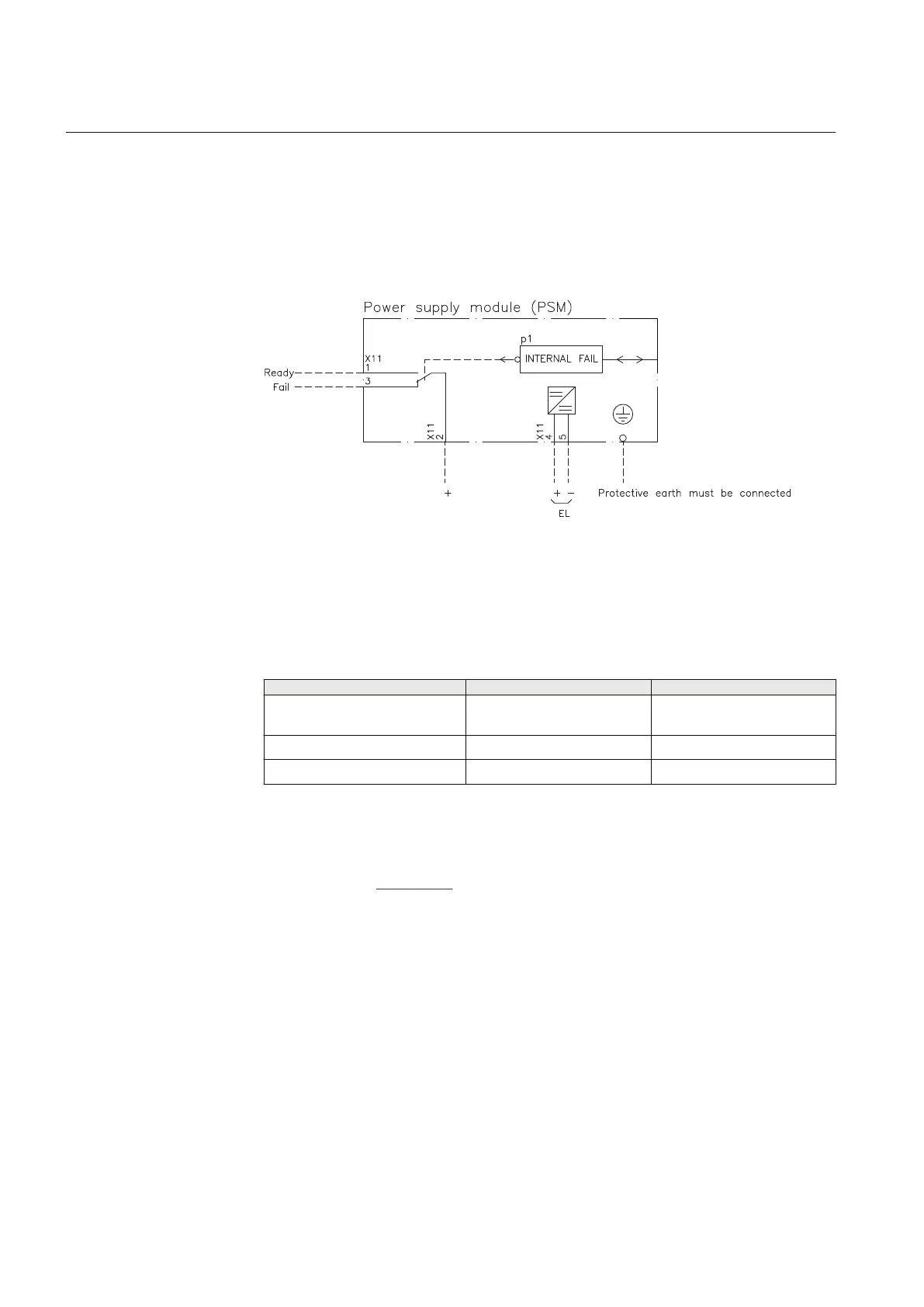
Connection diagram
M6377-8 v3
IEC08000476 V2 EN-US
Figure 396: PSM Connection diagram.
20.2.3.3 Technical data
SEMOD52801-1 v1
M12286-1 v6
Table 632: PSM - Power supply module
Quantity
Rated value Nominal range
Auxiliary DC voltage, EL (input) EL = (24-60) V
EL = (100-250) V
EL ±20%
EL ±20%
Power consumption 32 W typically -
Auxiliary DC power in-rush < 10 A during 0.1 s -
20.2.4 Local human-machine interface (Local HMI)
SEMOD56218-5 v4
Refer to section
Local HMI for information.
20.2.5 Transformer input module (TRM)
IP15581-1 v1
20.2.5.1 Introduction
M14875-3 v9
The transformer input module is used to galvanically separate and adapt the
secondary currents and voltages generated by the measuring transformers. The
module has twelve inputs in different combinations of currents and voltage inputs.
Alternative connectors of Ring lug or Compression type can be ordered.
Section 20 1MRK 506 382-UEN A
IED hardware
836 Line distance protection REL650 2.2 IEC
Technical manual

 Loading...


