Publication 1769-UM009B-EN-P - May 2002
1-2 Overview
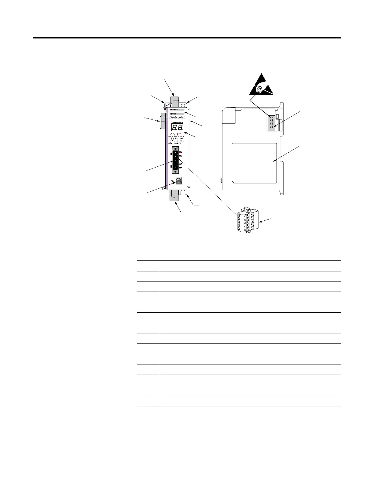
Identify Module Features
Use the following figure to identify the features of the scanner.
Table 1.1
Item Description
1 bus lever (with locking function)
2A upper DIN rail latch
2B lower DIN rail latch
3A upper panel mounting tab
3B lower panel mounting tab
4 Module and Network status LEDs
5 Address and Error numeric display
6 grounding screw
7A DeviceNet mating male receptacle
7B removable DeviceNet female connector
8A movable bus connector with female pins
8B bus connector with male pins
9 nameplate label
3A
1
2A
4
5
2B
6
7A
8A
8B
9
7B
3B
8B

 Loading...


