Publication 1769-UM009B-EN-P - May 2002
3-10 Installation and Wiring
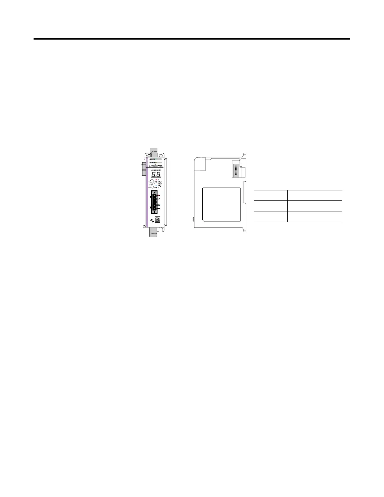
DIN Rail Mounting
The module can be mounted using the following DIN rails:
35 x 7.5 mm (EN 50 022 - 35 x 7.5) or 35 x 15 mm (EN 50 022 - 35 x
15).
Before mounting the module on a DIN rail, close the DIN rail latches.
Press the DIN rail mounting area of the module against the DIN rail.
The latches will momentarily open and lock into place. DIN rail
mounting dimensions are shown below.
Replacing the Scanner
Module within a System
The scanner can be replaced while the system is mounted to a panel
(or DIN rail) once power is removed.
1. Remove power. See important note on page 3-4.
2. Remove the DeviceNet cable from the scanner by removing the
DeviceNet connector.
3. Remove the upper and lower mounting screws from the scanner
(or open the DIN latches using a flat-blade screwdriver).
4. On the scanner to be replaced and the right-side adjacent
module (or end cap if the scanner is the last module in the
bank), move the bus levers to the right (unlock) to disconnect
the scanner from the adjacent modules.
5. Gently slide the disconnected scanner module forward.
Table 3.3
Dimension Height
A 118 mm (4.65 in.)
B 59 mm (2.325 in.)

 Loading...


