Publication 1769-UM009B-EN-P - May 2002
3-12 Installation and Wiring
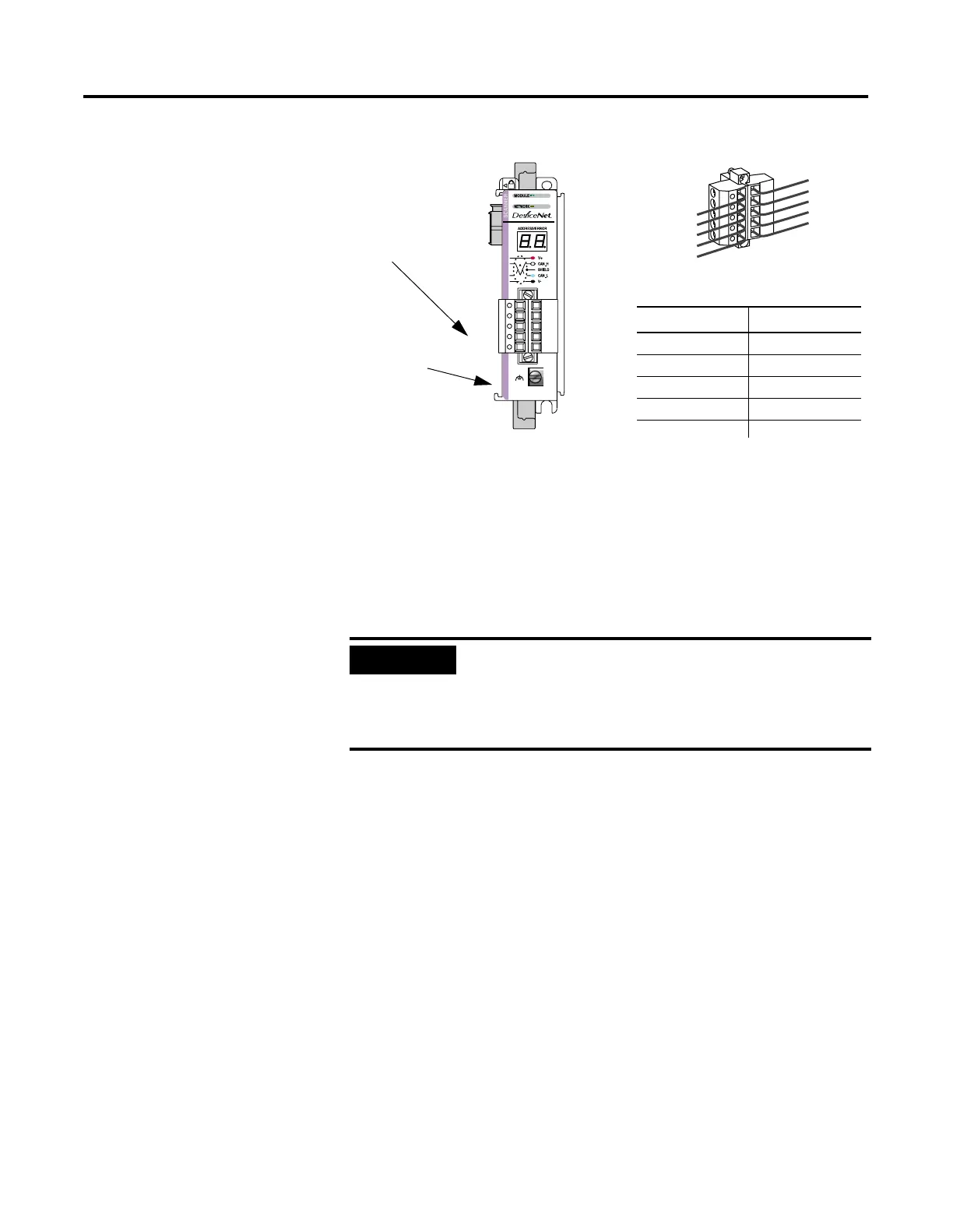
DeviceNet Wiring
1. Connect the DeviceNet cable to the removable connector as
shown.
2. Insert the removable female connector into the mating male
connector on the DeviceNet scanner module.
3. Screw the removable connector to the scanner case with the
upper and lower mounting screws. Screw torque is 0.6 to 0.7
Nm (5 to 6 in-lbs).
Scanner Module Power-Up
When power is applied via the Compact I/O bus, the scanner module
goes through a self test sequence. Upon successful completion of the
self test, the scanner is ready to communicate.
The default scanner settings are:
• baud rate = 125K
• node address = 63
Use your configuration software to change the baud rate and node
address.
What’s Next?
The next step is to configure the scanner and perform I/O data
mapping through RSNetWorx.
IMPORTANT
If the 1769-SDN is the first or last device connected
to the DeviceNet network trunkline, be sure to add a
termination resistor (120
Ω 1% ≥ ¼W resistor,
Allen-Bradley part number 1485A-C2) across the Blue
(CAN Low) and White (CAN High) wires.
DeviceNet
Connector
Table 3.4
Connect
(1)
To
Red Wire V+
White Wire CAN High
Bare Wire Shield
Blue Wire CAN Low
Black Wire V-
Grounding Screw
Use #14 AWG
wire to connect
to panel ground.

 Loading...


