Publication 1769-UM009B-EN-P - May 2002
Installation and Wiring 3-7
8. Lock the end cap bus terminator (G).
System Mounting
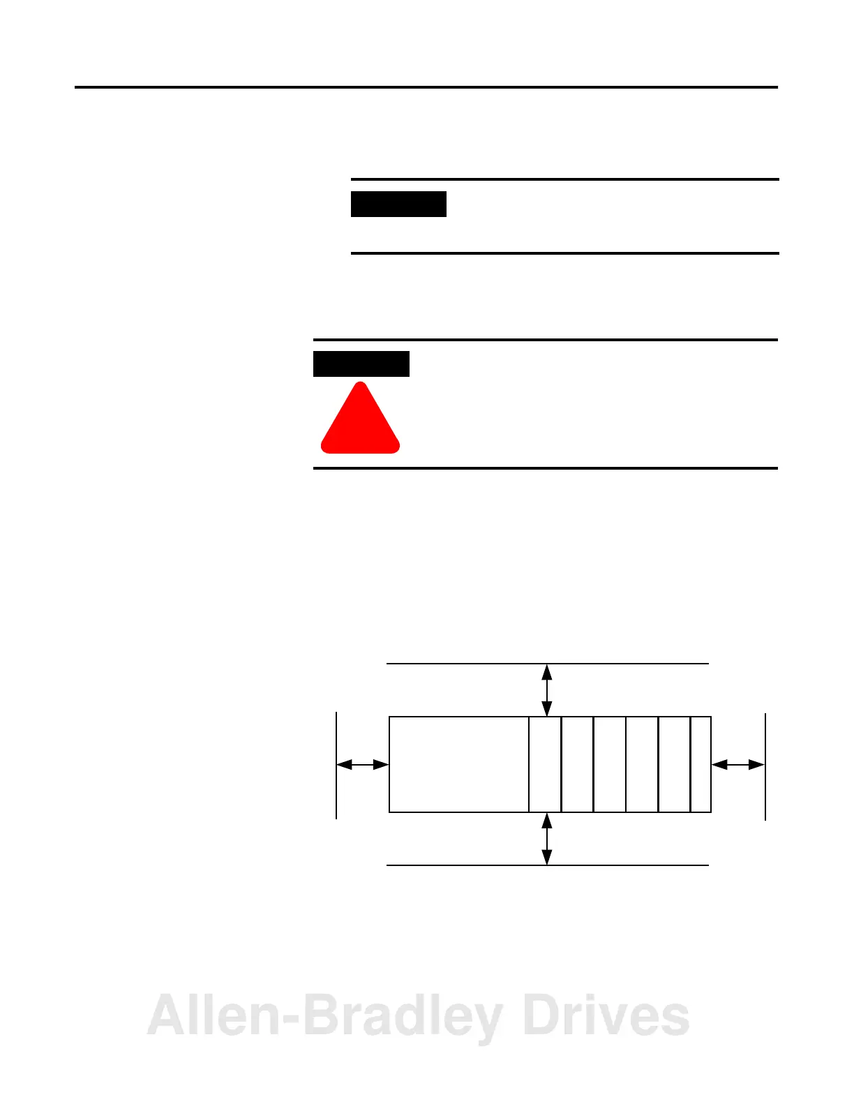
Minimum Spacing
Maintain spacing from enclosure walls, wireways, adjacent equipment,
etc. Allow 50 mm (2 in.) of space on all sides for adequate ventilation,
as shown below:
Allow at least 110 mm (4.33 in.) of enclosure depth to accommodate
the module and the DeviceNet connector.
IMPORTANT
A 1769-ECR or 1769-ECL right or left end cap
must be used to terminate the end of the serial
communication bus.
ATTENTION
!
During panel or DIN rail mounting of all devices, be
sure that all debris (metal chips, wire strands, etc.) is
kept from falling into the module. Debris that falls
into the module could cause damage at power up.
Host Controller
Compact I/O
Compact I/O
Compact I/O
Compact I/O
Compact I/O
End Cap
Side Side
Top
Bottom
Allen-Bradley Drives

 Loading...


