Publication 1769-UM009B-EN-P - May 2002
5-2 DeviceNet I/O Image
Status Structure
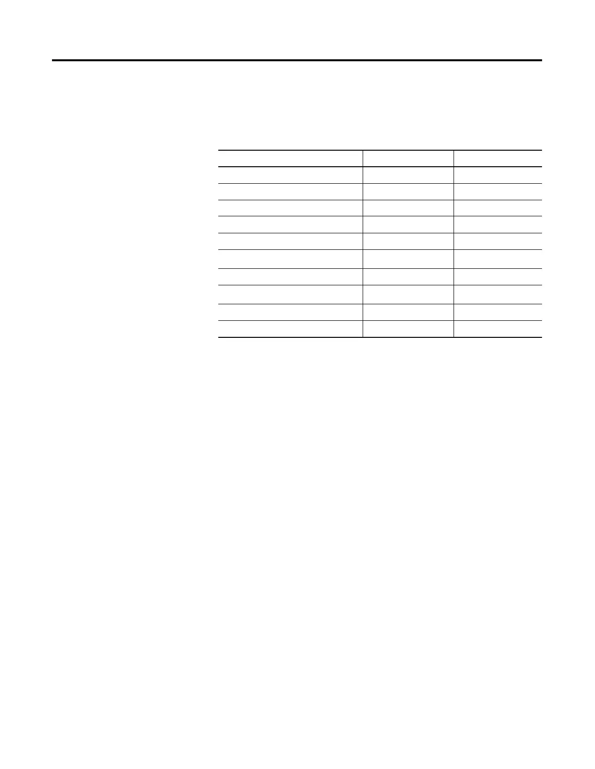
The first area of the input image is the Status Structure and is
illustrated in Table 5.2. The status words are described in more detail
in the following sections
Scan Counter
This 32-bit unsigned value is incremented each time the DeviceNet
network is scanned. The value will automatically roll over to zero and
continue counting.
Table 5.2 Status Structure
Description Words Data Type
Scan Counter 0 and 1 2 words
Device Failure Array 2 to 5 64-bit array
Autoverify Failure Array 6 to 9 64-bit array
Slave Device Idle Array 10 to 13 64-bit array
Active Node Array 14 to 17 64-bit array
Reserved
(1)
(1)
DO NOT manipulate Reserved Bits. Doing so may interfere with future compatibility.
18 and 19 4-byte array
Scanner Status 20 and 21 4-byte array
Reserved Array
(1)
22 to 31 20-byte array
Device Status Array 32 to 63 64-byte array
Module Status Register 64 and 65 2 words

 Loading...


