132 Rockwell Automation Publication 750-IN001P-EN-P - April 2017
Chapter 3 Lift and Mount the Drive
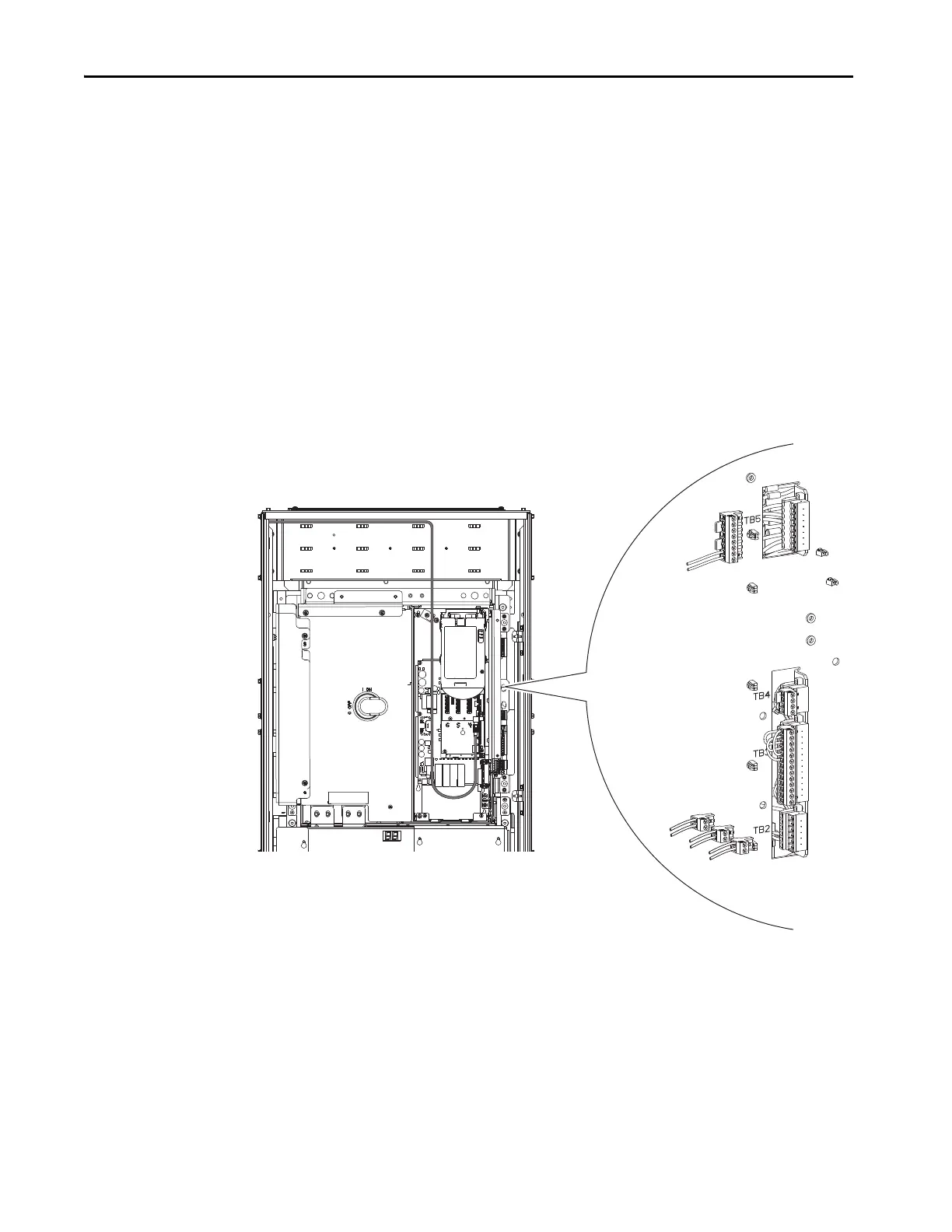
Common DC Input Drives
1. Disconnect the cabinet fan /cabinet blower assembly harnesses from
TB2-5 and TB2-6 (see number 1).
2. Disconnect the 120/240V control power input harness from TB2-3 and
TB2-4 (see number 2).
3. Disconnect 120V UPS control power input (if used) from TB2-1 and
TB2-2 (see number 3).
4. Disconnect the digital I/O wiring (if used) from TB3 (see number 4).
5. Disconnect the door interlock wiring (if used) from TB4 (see number
5).
6. Disconnect the 120V UPS control power output wiring (if used) from
TB5 (see number 6).
 Loading...

