Rockwell Automation Publication 750-IN001P-EN-P - April 2017 265
I/O Wiring Chapter 5
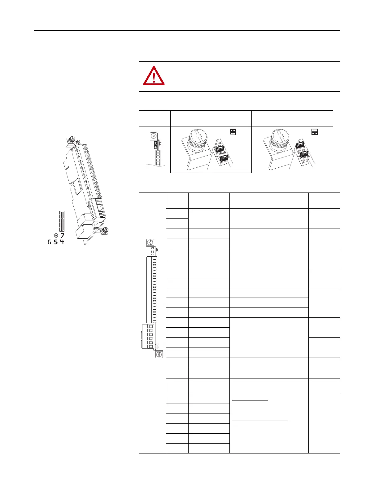
22-Series I/O Option Module
This section provides details for the 22-Series I/O option module.
Table 78 - Input Mode Jumpers
Table 79 - TB1 Terminal Designations
ATTENTION: When used in an Integrated Motion on EtherNet/IP networks
application for Firmware, versions 12 and later, the 22-series I/O module
must be installed only in port 7.
20-750-2262C-2R (24 Volts DC)
20-750-2263C-1R2T (24 Volts DC)
20-750-2262D-2R (120 Volts AC)
Jumper
Position
Voltage Mode Current Mode
Terminal Name Description Related
Parameter
(5)
Sh Shield Terminating point for wire shields when an
EMC plate or conduit box is not installed.
Sh
Ptc– Motor PTC (–) Motor protection device (Positive
Temperature Coefficient).
(2)
40
On port X
Ptc+ Motor PTC (+)
Ao0– Analog out 0 (–) Bipolar, ±10V, 11 bit and sign, 2 k Ω
minimum load.
4…20 mA, 11 bit and sign, 400 Ω
maximum load.
75
On port X
Ao0+ Analog out 0 (+)
Ao1– Analog Out 1 (–) 85
On port X
Ao1+ Analog Out 1 (+)
–10V –10V reference 2k Ω minimum.
10VC 10V common For (–) and (+) 10V references.
+10V +10V reference 2k Ω minimum.
Ai0– Analog input 0 (–) Isolated
(3)
, bipolar, differential, 11 bit and
sign.
Voltage Mode: ±10V at 88k Ω input
impedance.
Current Mode: 0…20 mA at 93 Ω input
impedance.
50, 70
On port X
Ai0+ Analog input 0 (+)
Ai1– Analog Input 1 (–) 60, 70
On port X
Ai1+ Analog Input 1 (+)
24VC 24V common Drive supplied logic input power.
200 mA max per I/O module
600 mA max per drive
+24V +24V DC
Di C Digital input
common
Common for Digital inputs 0…5
Di 0 Digital input 0
(1)
24V DC (30V DC max) – Opto isolated
High state: 20…24V DC 11.2 mA DC
Low state: 0…5V DC
120V AC (132V AC max) 50/60 Hz
(4)
– Opto
isolated
High state: 100…132V AC
Low state: 0…30V AC
1
On port X
Di 1 Digital input 1
(1)
Di 2 Digital input 2
(1)
Di 3 Digital input 3
(1)
Di 4 Digital input 4
(1)
Di 5 Digital input 5
(1)
Sh
Sh
PTC–
PTC+
Ao0–
Ao0+
Ao1–
Ao1+
–10V
10VC
+10V
Ai0–
Ai0+
Ai1–
Ai1+
24VC
+24V
DiC
Di0
Di1
Di2
Di3
Di4
Di5
 Loading...

