EasyManuals Logo
Home>Allen-Bradley>Controller>20F

Allen-Bradley 20F Installation Instructions

Allen-Bradley 20F
320 pages
To Next Page IconTo Next Page
To Previous Page IconTo Previous Page
Page #264 background imageLoading...
Page #264 background image
264 Rockwell Automation Publication 750-IN001P-EN-P - April 2017
Chapter 5 I/O Wiring
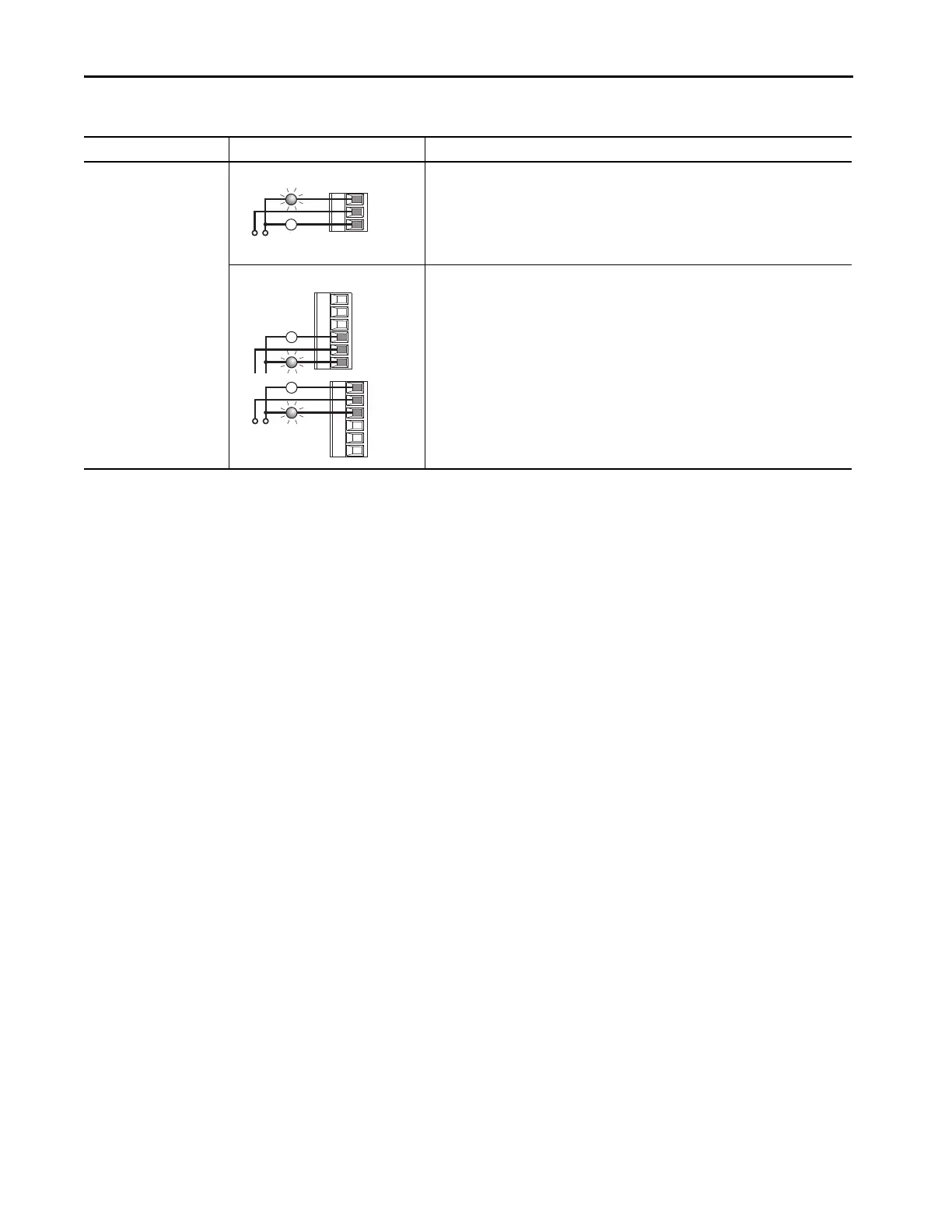
Table 77 - 11-Series I/O Option Module Relay Wiring Examples
Input/Output Connection Example Required Parameter Changes
Relay Output
External supply
753 Main Control Board • Set selection
Port 0: P230 [RO0 Sel] = Port 0: P935 [Drive Status 1], bit 7 = Faulted
•View results
Port 0: P225 [Dig Out Sts]
11-Series I/O Module • Set selection
Port X (11-Series I/O Module): P10 [RO0 Sel] = Port 0: P935 [Drive Status 1], bit 7 = Faulted
•View results
Port X (11-Series I/O Module): P5 [Dig Out Sts]
Power
Source
R0NC
R0C
R0NO
Power
Source
or
R0NO
R0C
R0NC
R1NO
R1C
R1NC

Table of Contents

Other manuals for Allen-Bradley 20F

Questions and Answers:

Question and Answer IconNeed help?

Do you have a question about the Allen-Bradley 20F and is the answer not in the manual?

Allen-Bradley 20F Specifications

General IconGeneral
BrandAllen-Bradley
Model20F
CategoryController
LanguageEnglish

Related product manuals