EasyManuals Logo
Home>Allen-Bradley>Controller>20F

Allen-Bradley 20F Installation Instructions

Allen-Bradley 20F
320 pages
To Next Page IconTo Next Page
To Previous Page IconTo Previous Page
Page #150 background imageLoading...
Page #150 background image
150 Rockwell Automation Publication 750-IN001P-EN-P - April 2017
Chapter 3 Lift and Mount the Drive
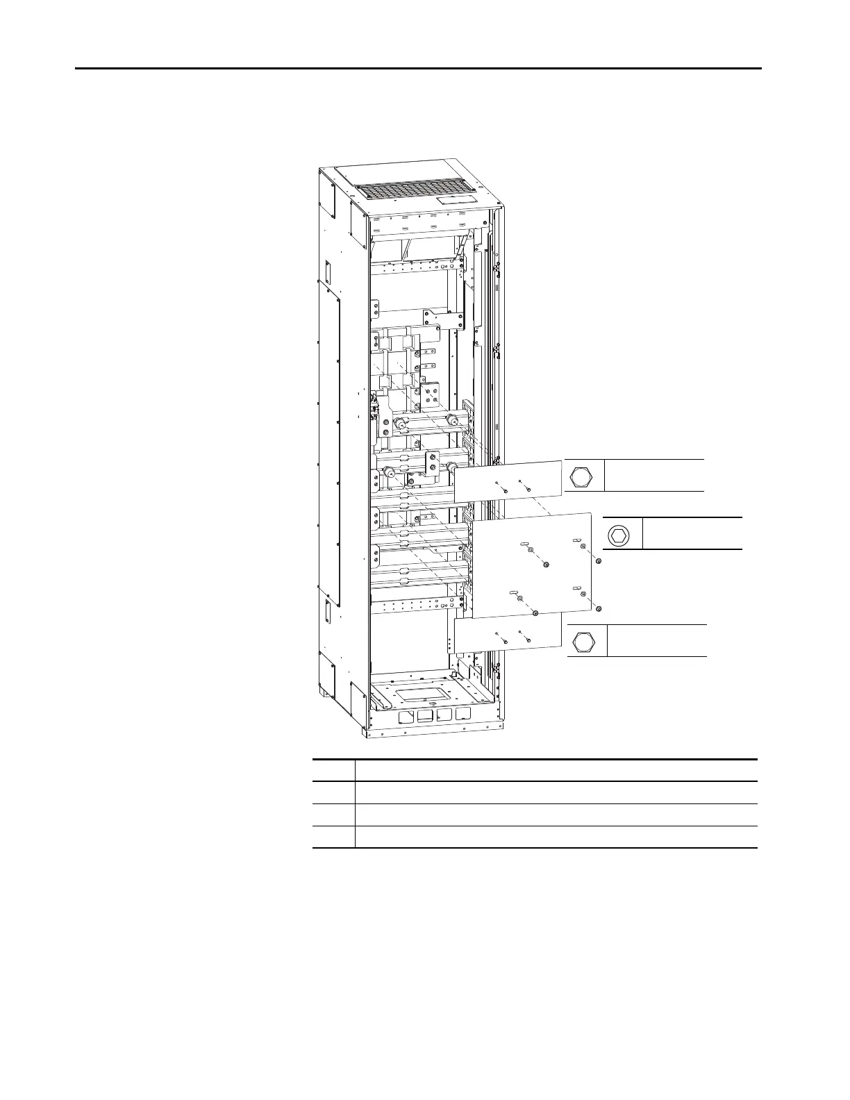
Remove DC Back Bus Guard –
Common DC Input Drives
To complete the power wiring connections in the common DC input drive
cabinet, remove the DC back bus guard to access the power terminals (see
number 2).
No. Description
1 120/240V control rail guard
2 DC back bus guard
3 120V interruptible power supply (UPS) rail guard
1
2
3
T45
5.1 N•m (45 lb•in)
7/16 in.
5.1 N•m (45 lb•in)
7/16 in.
5.1 N•m (45 lb•in)

Table of Contents

Other manuals for Allen-Bradley 20F

Questions and Answers:

Question and Answer IconNeed help?

Do you have a question about the Allen-Bradley 20F and is the answer not in the manual?

Allen-Bradley 20F Specifications

General IconGeneral
BrandAllen-Bradley
Model20F
CategoryController
LanguageEnglish

Related product manuals