Home
Allen-Bradley
Controller
20F
Allen-Bradley 20F Installation Instructions
5
of 1
of 1 rating
320 pages
Give review
Manual
Specs
To Next Page
To Next Page
To Previous Page
To Previous Page
Loading...
Rockwell Automation Publ
ication 750-IN001P-EN-P -
April 2017
45
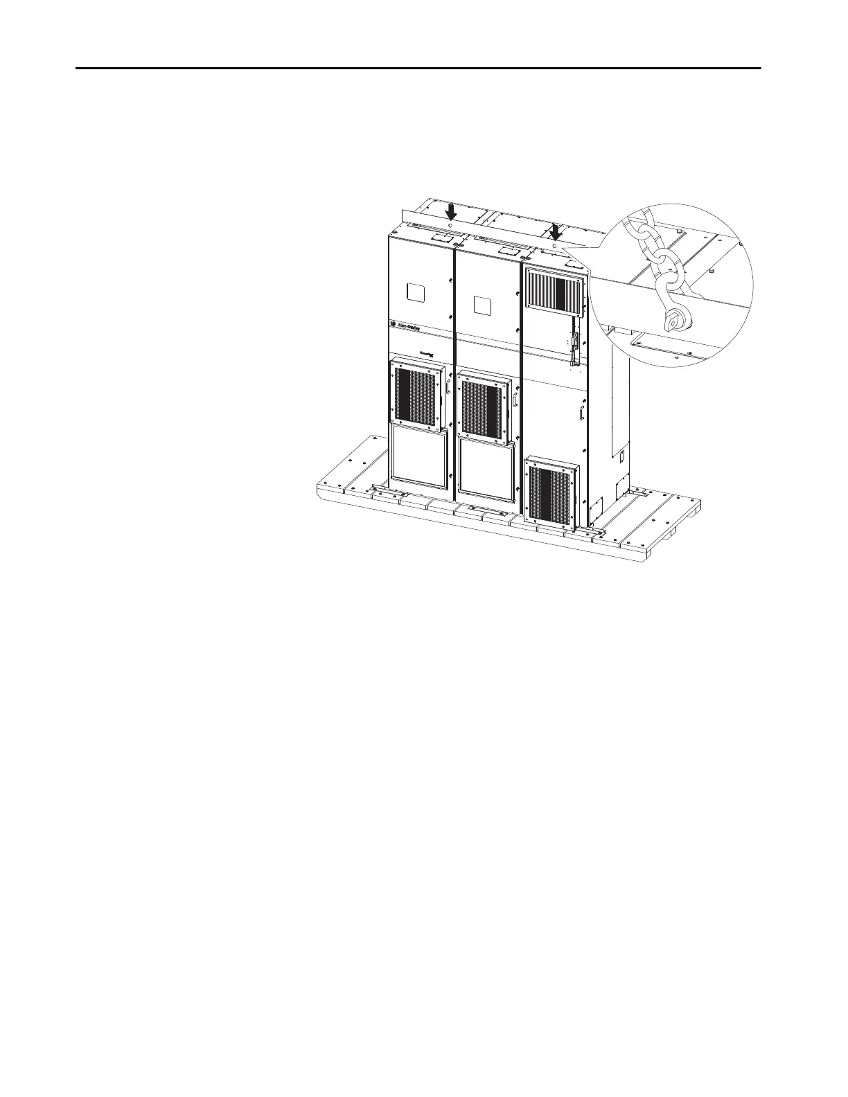
Lift and Mount the Drive
Chapte
r 3
Enclosure Codes J, K, and Y
F
ollow t
hese g
uidelines for driv
es wit
h enclos
ur
e code J
, H, and Y
.
Figure
22 - Flo
or Moun
t Frame
9 with
Cabi
net O
ption
s Bay Lift
Points – Two Places
44
46
Table of Contents
Default Chapter
3
Table of Contents
3
Preface
9
Summary of Changes
9
Installation Instructions in Other Languages
10
Commonly Used Tools
11
Installation and Service Tools
11
Line to Load Installation Guidelines
12
Additional Resources
14
Chapter 1 Qualified Personnel
15
Personal Safety
15
Read the General Precautions
15
Class 1 Light-Emitting Diode Product
16
Product Safety
16
Prepare for Installation
17
Chapter 2 Wall Mount Frames 1
19
Floor Mount Frames 8
21
CE Conformity
22
Low Voltage Directive
22
EMC Directive
22
General Considerations
22
Installation Requirements Related to en 61800-5-1
23
And the Low Voltage Directive
23
Installation Requirements Related to en 61800-3
24
And the EMC Directive
24
Access Panels, Covers, and Doors
28
Minimum Clearances
36
Environmental Specifications
37
Mounting Considerations
37
Wall Mount Frames 1
37
Floor Mount Frames 8
37
All Mounting Styles and Frames
37
Chapter 3 Drive Weights
39
Lift and Mount the Drive
39
Recommended Mounting Hardware
40
Attach Lifting Hardware
41
Enclosure Code F
41
Enclosure Code N
42
Enclosure Code G
43
Open Type Drive (Removed from Cabinet)
43
Enclosure Codes B and L
44
Enclosure Codes J, K, and y
45
Release Floor Mount Drive Cabinet from Shipping Skid
46
Remove Drive Cabinet Lifting Angle
47
And Exhaust Hood
48
Install IP54, NEMA 12 Cabinet Blower Assembly
48
Or Optional Exhaust Hood
48
And Wiring Bay
49
Position the Drive Cabinets and Cabinet Options Bay
49
Position the Wiring Bay
51
Join the Cabinets
54
Install Floor Mount Drive with Cabinet Options Bay
49
Approximate Dimensions - Wall Mount Frames 1
57
Floor Mount Frames 8
57
Cabinet Options
88
Release Drive Assembly from Cabinet
124
Disconnect Drive Control Pod Wiring Connections
127
Fiber-Optic Cables
127
Disconnect Wire Connections - no Drive Control Pod
129
Disconnect Control and Power Wire Harnesses
131
AC Input Drives
131
Disconnect DC Bus Fuse Wire Harness
131
AC Input Drives Floor Mount Frames 9 and Larger
131
Common DC Input Drives
132
Release Cabinet Options Assembly from Cabinet
133
Prepare the Roll-Out Cart
135
Adjust Roll-Out Cart Height Using Threaded Studs
137
And Nuts
137
Adjust Roll-Out Cart Height Using Spacers
138
Adjust Roll-Out Cart Reach
143
Remove Drive Assembly or Cabinet Options Assembly
144
Drive Assembly - Floor Mount Frames 8
147
Cabinet Options Assembly - Floor Mount Frames 9 and 10
148
Remove DC Back Bus Guard - Common DC Input Drives
150
Reinstall Drive Assembly or Cabinet Options Assembly
151
Chapter 4 Grounding Requirements
153
Recommended Grounding Scheme
153
Shield Termination - SHLD
154
RFI Filter Grounding
154
Power Wiring
153
Motor Considerations
155
Power Cable Types Acceptable for 200
155
Wire Recommendations
155
Terminal Block Specifications
155
Three-Phase Terminal Locations
157
Wall Mount Frames 1
159
Rockwell Automation Publication 750-IN001P-EN-P - April
160
Terminal Locations
161
Power Terminals
163
Floor Mount Frames 8
164
Floor Mount Cabinet Options Bay
167
Floor Mount Frames 8
169
Floor Mount Frames 8
170
Additional Power Terminal L-Brackets
170
Frames 8 and Larger
172
Recommended Motor Cable Spacing - Floor Mount
172
Fuse and Circuit Breaker Ratings
175
Motor Overload Protection
192
Short Circuit Current Rating
192
Short Circuit Current Ratings - Floor Mount Drives
192
With Cabinet Options
192
Input Contactor Precautions
196
Applying and Removing Power
197
Bypass Contactor Precaution
197
Drives with Cabinet Options
197
Power Disconnects
197
Contactors
198
Reactors
198
Terminal Blocks and Other Cabinet Parts
198
Transformer Panel
199
Power Wiring Schematic
199
Output Contactor Precaution
197
Input Power Circuit Breakers and Disconnect Switches
200
Cabinet Options Bay Accessories
204
Drive Power Jumper Configuration
215
Capacitor Circuits
215
Wall Mount Frames 2
218
Removal and Storage
219
Wall Mount Frames 1, 6, and 7 Power Jumper
219
Wire Removal and Storage
219
Floor Mount Frames 8
222
Removal and Storage
222
I/O Wiring
225
Chapter 5 I/O Terminal Blocks
226
I/O Wiring I/O Terminal Blocks
226
Access Drive Control Pod
228
Powerflex 753 Main Control Board
232
Powerflex 755 Main Control Board
235
Wall Mount Frames 1
235
Floor Mount Frames 8
236
Hardware Enable Circuitry
237
Safety Enable Circuitry
239
Powerflex 755 Fiber-Optic Interface Board
240
AC Input Drive Control and Power Terminal Block
241
Shunt Trip Contact Operation
242
DC Precharge Board
243
V Output Wiring for Drive Control
244
DC Input Drives
246
DC Input Drives
247
DC Input Drives
248
Powerflex 753 Main Control Board I/O Wiring Examples
249
Drive Device Ports
252
Option Module Installation
253
Series I/O Option Module
254
Series I/O with ATEX Option Module
256
Series I/O Option Module Wiring Examples
257
Series I/O Option Module
265
Series I/O Option Module Wiring Examples
267
Safe Torque off Option Module
272
Integrated Safety - Safe Torque off Option Module
273
Cabling
274
Safe Speed Monitor Option Module
275
Installation Guidelines
276
Auxiliary Power Supply Option Module
277
Devicenet Option Module
279
Controlnet Option Module
280
Dual-Port Ethernet/Ip Option Module
281
PROFIBUS Option Module
282
Bacnet/Ip Option Module
283
COMM Carrier
284
Single Incremental Encoder Option Module
285
Dual Incremental Encoder Option Module
287
Option Module Connections
288
Option Module Connections
290
Powerflex 755 Drives
291
Rockwell Automation Publication 750-IN001P-EN-P - April
291
Universal Feedback Option Module - Only
291
Feedback Device Resolution
294
Motor Feedback Wiring Examples
294
Motor Power Cables
294
Control Pod Cable Routing
304
Floor Mount Frames 8
304
Cabinet Options
305
Cabinet Options
307
Control Wiring - Current Frame 8 Drives with
307
Cabinet Options
308
Enclosure Options - Floor Mount Frames 8
310
NEMA/UL Type 1 Enclosure - 2500 MCC Style Cabinet
310
NEMA Type 12 Enclosure - 2500 MCC Style Cabinet
310
Chapter 6 Supporting Documentation
311
Configure Option Modules for Integrated Motion
311
Index
313
Other manuals for Allen-Bradley 20F
Installation Instructions Manual
8 pages
5
Based on 1 rating
Ask a question
Give review
Questions and Answers:
Need help?
Do you have a question about the Allen-Bradley 20F and is the answer not in the manual?
Ask a question
Allen-Bradley 20F Specifications
General
Brand
Allen-Bradley
Model
20F
Category
Controller
Language
English
Related product manuals
Allen-Bradley 2080-IF4
118 pages
Allen-Bradley 2080-OB4
118 pages
Allen-Bradley 2080-OW4I
118 pages
Allen-Bradley 2080-IQ4OB4
118 pages
Allen-Bradley 2080-LC20-20QBB
212 pages
Allen-Bradley 2080-SERIALISOL
118 pages
PowerFlex 20-750-S1
302 pages
PowerFlex 20-750-APS
302 pages
PowerFlex 20-750-ENC-1
302 pages
PowerFlex 20-750-ENETR
302 pages
PowerFlex 20-750-UFB-1
302 pages
PowerFlex 20-750-20COMM
302 pages
 Loading...

