226 Rockwell Automation Publication 750-IN001P-EN-P - April 2017
Chapter 5 I/O Wiring
I/O Terminal Blocks
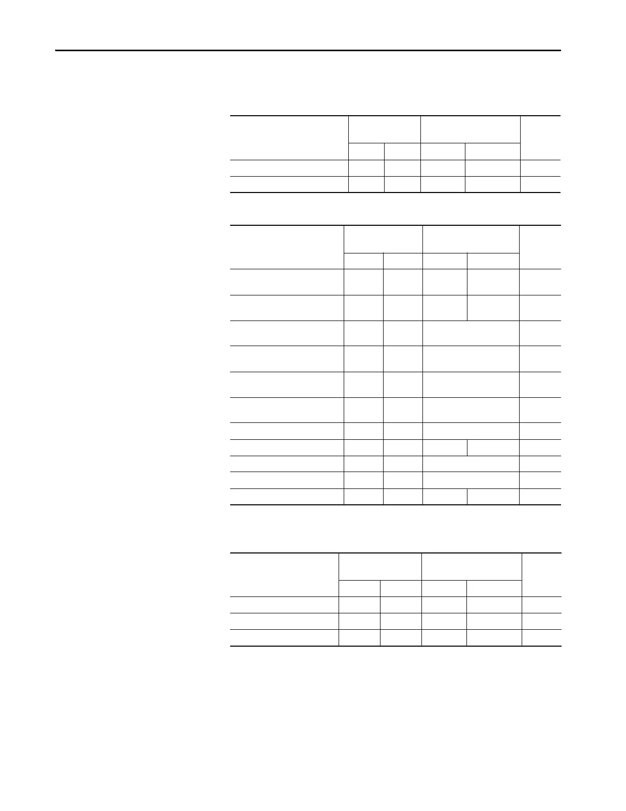
This section provides specifications for the I/O terminal blocks.
Table 47 - Main Control Board I/O Terminal Block Specifications
Table 48 - Option Module I/O Terminal Block Specifications
Table 49 - Three-phase Drive Assembly I/O Terminal Block and Connector Specifications
Name Wire Size Range
mm
2
(AWG)
Torque
N•m (lb•in)
Strip
Length
mm (in.)
Max Min Max Recommended
753 Control Module TB1, TB2, and TB3 2.5 (14) 0.3 (28) 0.25 (2.2) 0.2 (1.8) 6 (0.24)
755 Control Module TB1 2.5
(14) 0.3 (28) 0.25 (2.2) 0.2 (1.8) 6 (0.24)
Name Wire Size Range
mm
2
(AWG)
Torque
N•m (lb•in)
Strip
Length
mm (in.)
Max Min Max Recommended
22-Series I/O Modules TB1 with
Screw Terminals
2.5 (14) 0.3 (28) 0.25 (2.2) 0.2 (1.8) 6 (0.24)
22-Series I/O Modules TB2 with
Screw Terminals
4.0 (12) 0.25
(24) 0.5 (4.4) 0.4 3.5) 7 (0.28)
11-Series I/O Module TB1 with
Tension Clamp Terminals
2.5 (14) 0.13 (26) N/A 10 (0.39)
11-Series I/O Module TB2 with
Tension Clamp Terminals
4.0 (12) 0.25 (24) N/A 10 (0.39)
Safe Torque Off
(1)
(cat. no. 20-750-S)
(1) Shielded cable that is required.
0.8 (18) 0.3 28) N/A 10 (0.39)
Integrated Safety - Safe Torque Off
(1)
(cat. no. 20-750-S3)
0.8 (18) 0.3 28) N/A 10 (0.39)
Single Incremental Encoder 0.8 (18) 0.3 (28) N/A 10 (0.39)
Safe Speed Monitor TB1 and TB2
(1)
2.5 (14) 0.25
(24) 0.25 (2.2) 0.2 (1.8) 6 (0.24)
Dual Incremental Encoder 0.8 (18) 0.3 (28) N/A 10 (0.39)
755 Universal Feedback Module 0.8 (18) 0.3 (28) N/A 10 (0.39)
Auxiliary Power Supply TB1 2.5 (14) 0.3 (28) 0.25 (2.2) 0.2 (1.8) 6 (0.24)
Name Wire Size Range
mm
2
(AWG)
Torque
N•m (lb•in)
Strip
Length
Max Min Max Recommended
Converter TB1 and TB2 4.0 (12) 0.25 (24) 0.5 (4.4) 0.4 (3.5) 7 (0.28)
Fiber Interface PCB Connector P13 4.0 (12) 0.25 (24) 0.5 (4.4) 0.4 (3.5) 7 (0.28)
Fiber Interface PCB Connector P14 2.5 (14) 0.3 (28) 0.25 (2.2) 0.2 (1.8) 6 (0.24)
 Loading...

