Rockwell Automation Publication 750-IN001P-EN-P - April 2017 287
I/O Wiring Chapter 5
Dual Incremental Encoder
Option Module
This section provides details for the dual incremental encoder option module.
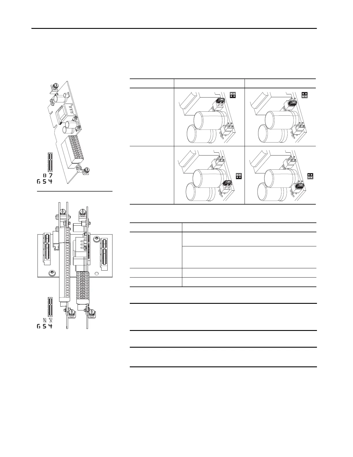
Table 110 - Dual Incremental Encoder Jumper Settings
Table 111 - Dual Incremental Encoder Specifications
20-750-DENC-1
20-750-S1
20-750-DENC-1
See the Important statements on this page.
Jumper Enabled Position Storage Position
P3 - Safety Jumper
Enables use with speed
monitoring safety option
(20-750-S1).
P4 -12V Jumper
Enables use with 12 volt
supply in “Enabled”
position and 5 volt
supply in “Storage”
position.
Consideration Description
Input Differential or Single Ended operation, Constant Current Sink operation,
approx. 10 mA
5V DC minimum to 15V DC maximum sourcing 10 mA
Minimum high state voltage of 3.5V DC
Maximum low state voltage of 0.4V DC
Maximum Cable Length 30 m (100 ft) at 5V, 183 m (600 ft) at 12V
Maximum Input Frequency 250 kHz
IMPORTANT PowerFlex 753 drives and PowerFlex 755 drives support the use of the Dual
Incremental Encoder option module when used with the Safe Speed
Monitor option module (catalog number 20-750-S1).
IMPORTANT When used with the Safe Speed Monitor option, both modules must be
installed on the same backplane using ports 4, 5, or 6.
P3
P4 P4
 Loading...

