244 Rockwell Automation Publication 750-IN001P-EN-P - April 2017
Chapter 5 I/O Wiring
Disconnect Switch (SW2) Operation
120V Output Wiring for Drive Control
The common DC input drive provides limited 120V control power for use
with the drive control pod option modules. For terminal block wiring
specifications, see Table 50 on page 227
.
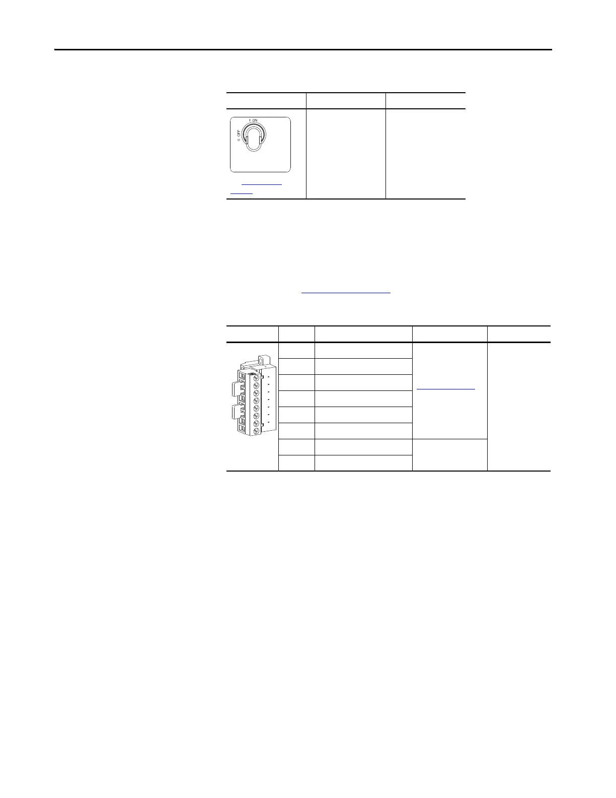
Table 68 - TB5 Terminal Designations
SW2 Is On Door Closed Door Open
See Figure 42 - on
page 77 for location.
Solenoid and door switch
circuits are energized.
Alarm is indicated.
Fixed I/O Terminal Name Description Rating
1 UPS 120V AC OUT HOT Jumper combinations
select the source of the
120V AC output for
drive control. See
Table 69 on page 245.
120V AC, 50/60 Hz,
0.4 A, 48VA
Fusing: 1 A, 600V,
Class CC, Time Delay
2 120V AC HOT
3 CONTROL 120V AC OUT HOT
4 UPS 120V AC OUT NEUTRAL
5 120V AC NEUTRAL
6 CONTROL 120V AC OUT NEUTRAL
7 120V AC OUT NEUTRAL Drive supplied 120V AC
output for drive control.
8 120V AC OUT HOT
 Loading...

