172 Rockwell Automation Publication 750-IN001P-EN-P - April 2017
Chapter 4 Power Wiring
Recommended Motor Cable
Spacing – Floor Mount
Frames 8 and Larger
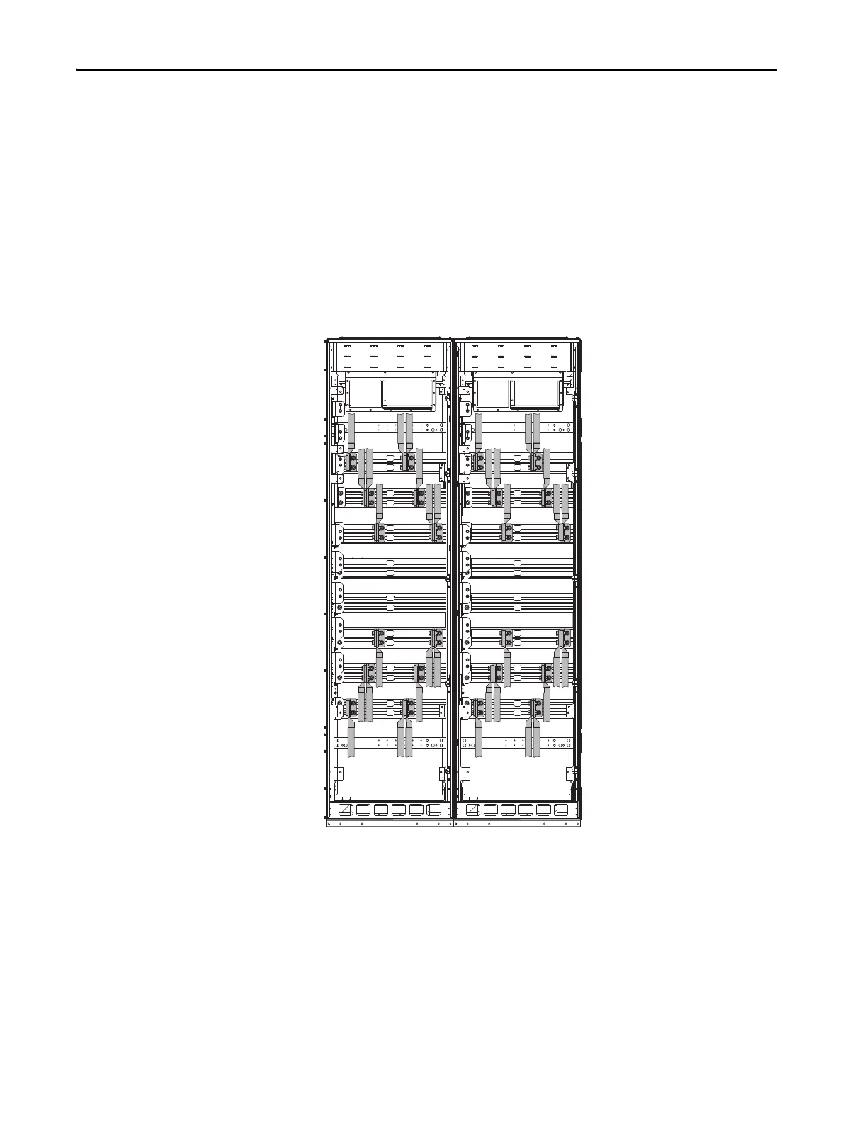
Frame 8 and larger drives typically require multiple conductors in parallel. The
installer determines the wire size, and number of conductors, based on drive
rated current, local codes, operating conditions, and specific application needs.
When using multiple conductors per phase, symmetrical spacing of the input
and output power cabling over the span of the bus bar for each phase is
recommended.
When using multiple conductors per phase, wires must be arranged so that
each conduit, bundle, or cable contains equal numbers of conductors from all
three phases.
Figure 106 - Recommended Cable Spacing Example – Floor Mount Frame 9 without Cabinet
Options Bay
 Loading...

