Rockwell Automation Publication 750-IN001P-EN-P - April 2017 245
I/O Wiring Chapter 5
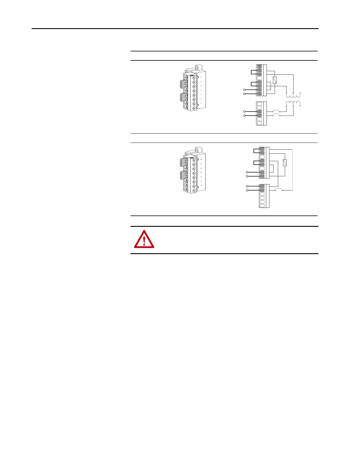
Table 69 - TB5 Jumper Settings
120V AC from Control Transformer
Factory Jumper Settings:
•TB5-2 and TB5-3
•TB5-5 and TB5-6
120V AC from User Supplied UPS
User Jumper Settings:
•TB5-1 and TB5-2
•TB5-4 and TB5-5
ATTENTION: Hazard of personal injury or equipment damage exists if
jumpers are incorrectly set. Verify that the jumpers are set for the correct
control scheme before energizing the circuit.
2
3
5
6
1
2
3
4
5
6
1
2
3
4
5
6
7
8
120V AC Output
Neutral
Hot
120V AC Input
Neutral
Hot
1 A
N 120 240
T1
1KVA
SW2
8
7
TB5
TB2
1
2
3
4
5
6
1
2
3
4
5
6
7
8
120V AC Output
Neutral
Hot
120V AC UPS Input
Neutral
Hot
1 A
SW2
TB5
TB2
6
 Loading...

