136 Rockwell Automation Publication 750-IN001P-EN-P - April 2017
Chapter 3 Lift and Mount the Drive
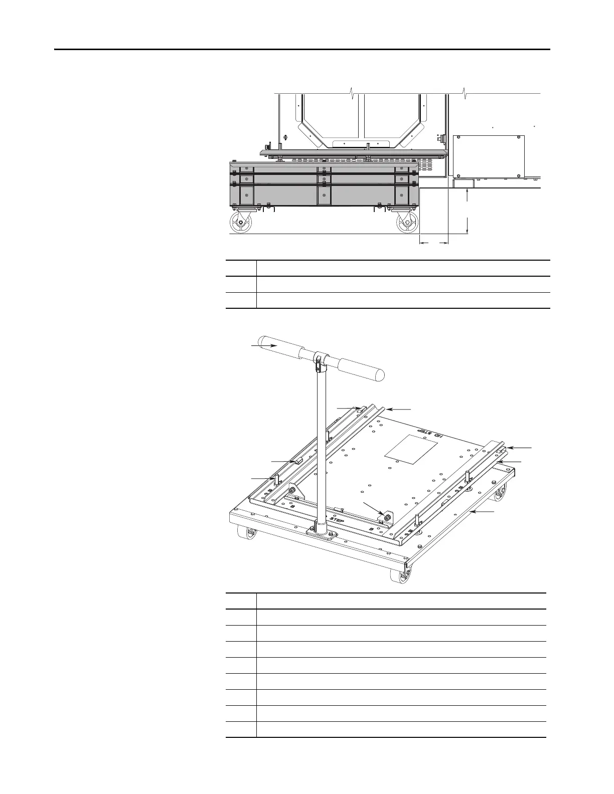
The roll-out cart can be adjusted for both reach and height.
Figure 91 - Roll-out Cart Features
No. Description
1 Adjustment for curb offset/reach: 0…114 mm (0…4.5 in.)
2 Adjustable curb height: 0…182 mm (0…7.2 in.)
No. Description
1 Threaded studs and nuts allow precision height and level adjustments (four positions)
2 Bubble levels help with fine adjustment of the cart deck (three positions)
3Handle
4 Retaining clips positively engage the cart with the drive cabinet (two positions)
5 Alignment track keeps the drive in the correct position
6Cart deck
7Cart chassis
8 Drive stop and capture screws
1
2
1
2
3
4
5
4
6
7
8
 Loading...

