Rockwell Automation Publication 750-IN001P-EN-P - April 2017 293
I/O Wiring Chapter 5
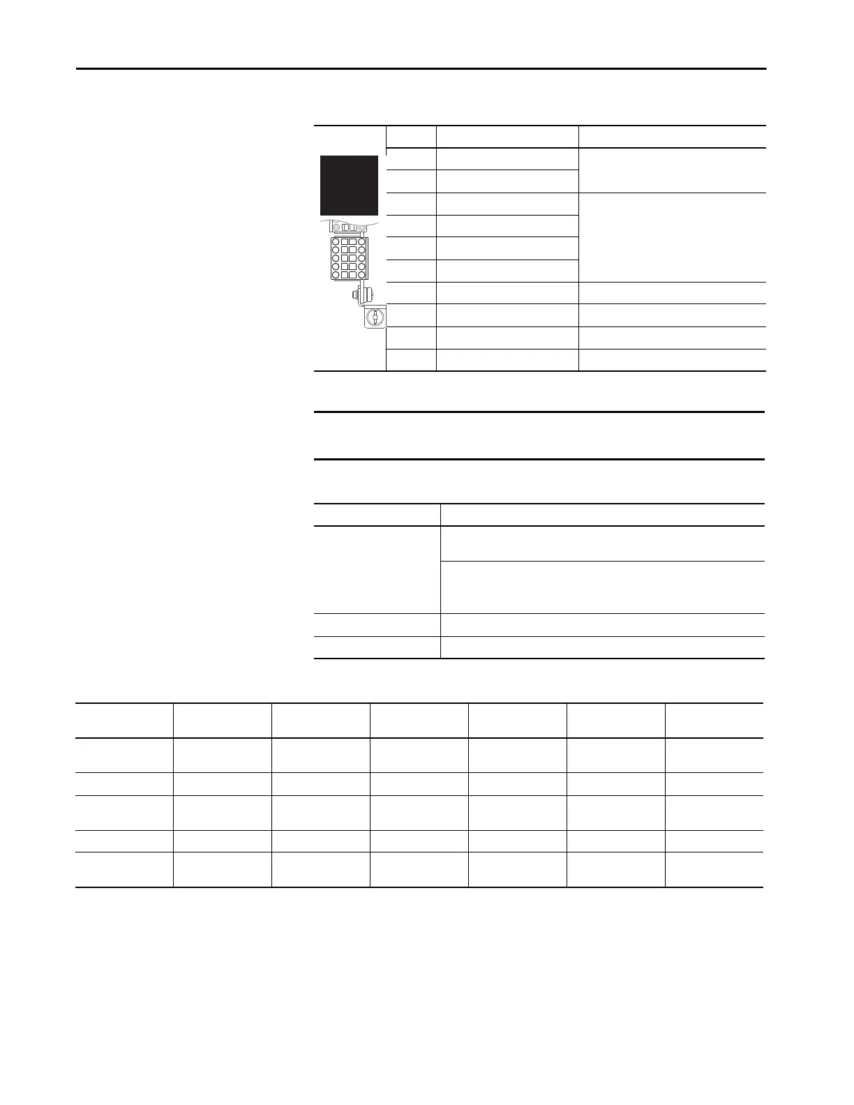
Table 116 - TB2 Terminal Designations
Table 117 - Universal Feedback Incremental AquadB Encoder
Table 118 - Supported Encoders
Terminal Name Description
-Hm Home Input (–) 12V DC at 9 mA to 24V DC at 40 mA
+Hm Home Input (+)
-R0 Registration Input 0 (–) Positive and negative encoder registration
terminals.
12V DC at 9 mA to 24V DC at 40 mA
+R0 Registration Input 0 (+)
-R1 Registration Input 1 (–)
+R1 Registration Input 1 (+)
-Yc Channel Y Clock (–) Negative clock terminal (channel Y)
+Yc Channel Y Clock (+) Positive clock terminal (channel Y)
-Yd Channel Y Data (–) Negative data terminal (channel Y)
+Yd Channel Y Data (+) Positive data terminal (channel Y)
IMPORTANT Only one linear feedback device can be connected to the option module.
Wire the device to either channel X on TB1, or channel Y on TB2.
Consideration Description
Input Differential or single-ended operation, constant current sink operation,
approx. 10 mA
3.5V DC minimum to 7.5V DC maximum sourcing 10 mA
Minimum high state voltage of 3.5V DC
Maximum low state voltage of 0.4V DC
Maximum cable length 30 m (100 ft) at 5V
Maximum input frequency 250 kHz
-Hm
-R0
-R1
-YC
-YD
+Hm
+R0
+R1
+YC
+YD
Consideration Heidenhain (EnDat) SSI Stegmann
(Hiperface)
BiSS Stahl (linear) Temposonics
(linear)
Encoder voltage
supply
5V at 250 mA 10.5V at 250 mA 10.5V at 250 mA 10.5V at 250 mA External Supplied 24V External Supplied 24V
High-resolution signal Sine/Cosine 1V P-P Sine/Cosine 1V P-P Sine/Cosine 1V P-P Sine/Cosine 1V P-P N/A N/A
Maximum cable
length
100 m (328.1) 100 m (328.1) 90 m (295.3) 100 m (328.1) 100 m (328.1) 100 m (328.1)
Update rate
(1)
102.4 μs 102.4 μs 102.4 μs 102.4 μs 0.5/1.0/1.5/2.0 ms 0.5/1.0/1.5/2.0 ms
Maximum input
frequency
163.8 kHz 163.8 kHz 163.8 kHz 163.8 kHz N/A N/A
(1) The universal feedback encoder option module acquires the position with the update rates displayed.
 Loading...

