EasyManuals Logo
Home>Allen-Bradley>Controller>20F

Allen-Bradley 20F Installation Instructions

Allen-Bradley 20F
320 pages
To Next Page IconTo Next Page
To Previous Page IconTo Previous Page
Page #55 background imageLoading...
Page #55 background image
Rockwell Automation Publication 750-IN001P-EN-P - April 2017 55
Lift and Mount the Drive Chapter 3
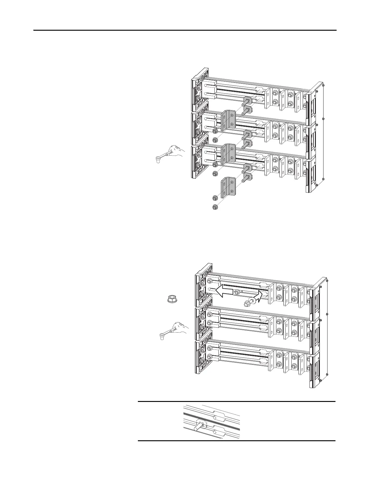
5. To access the channel notches, remove the left-most L-bracket from each
of the six wiring bay bus bars.
6. Insert the 12 carriage bolt assemblies into the 12 wiring bay bus bar
channels.
7. Slide the carriage bolt assemblies into the bus bar couplers on the left
and tighten.
IMPORTANT Verify that clamp fits squarely in the bus
bar channel.
17 mm
M10 x 1.5
38.0 N•m (336 lb•in)
17 mm

Table of Contents

Other manuals for Allen-Bradley 20F

Questions and Answers:

Question and Answer IconNeed help?

Do you have a question about the Allen-Bradley 20F and is the answer not in the manual?

Allen-Bradley 20F Specifications

General IconGeneral
BrandAllen-Bradley
Model20F
CategoryController
LanguageEnglish

Related product manuals