Publication 1756-UM001G-EN-P - January 2007
Configure Redundancy 113
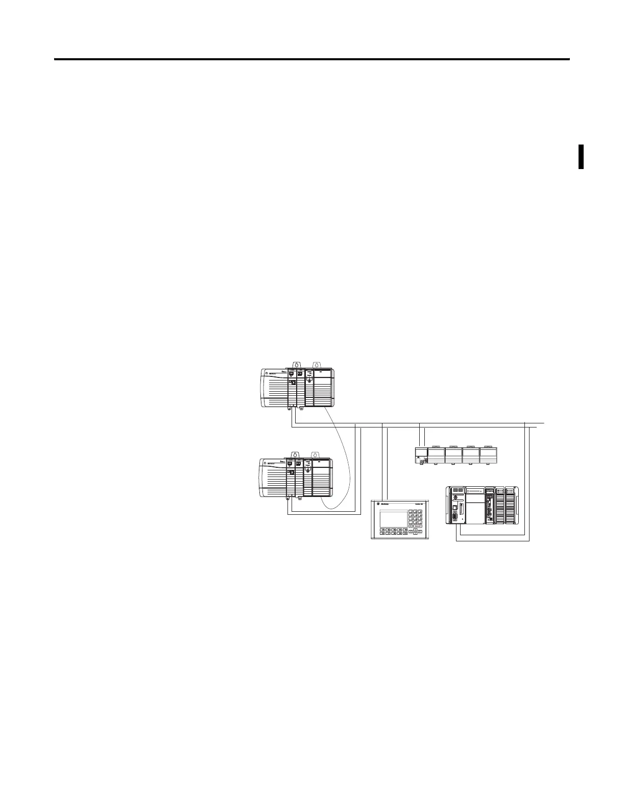
Build a Redundant System
To build a typical redundant system, perform this procedure.
1. Start with any ControlLogix chassis.
2. Add a 1756-L55, 1756-L61, 1756-L62, 1756-L63, or 1756-L64
controller.
3. Add one or more ControlNet (1756-CNB, 1756-CNBR) or
EtherNet/IP (1756-ENBT) communication modules.
4. Add one 1757-SRM redundancy module.
5. Set up a second chassis that is identical to the first chassis.
6. Connect the 1757-SRM redundancy modules in both chassis.
7. Add I/O modules, operator interfaces, and other devices to the
ControlNet network.
Redundant System
Primary Controller
Secondary Controller
HMI Device
Remote I/O
Remote Controller
 Loading...
