182 Rockwell Automation Publication 1756-RM003N-EN-P - October 2011
Chapter 4 Input/Output Instructions (MSG, GSV, SSV, IOT)
Specify PLC-3 Messages
The PLC-3 message types are designed for PLC-3 processors.
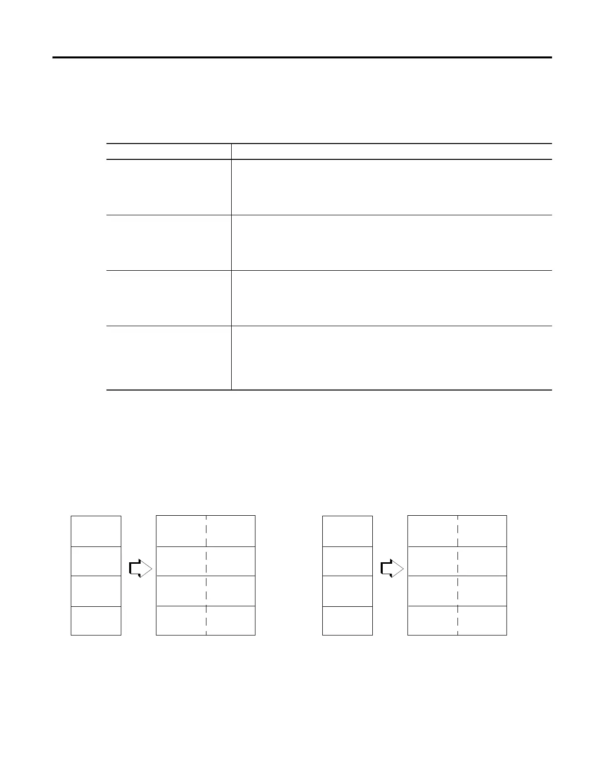
The following diagrams show how the typed and word-range commands differ.
The example uses read commands from a PLC-3 processor to a Logix5000
controller.
Select this command If you want to
PLC3 Typed Read Read integer or REAL type data.
For integers, this command reads 16-bit integers from the PLC-3 processor and stores them in
SINT, INT, or DINT data arrays in the Logix5000 controller and maintains data integrity.
This command also reads floating-point data from the PLC-3 and stores it in a REAL data type tag
in the Logix5000 controller.
PLC3 Typed Write Write integer or REAL type data.
This command writes SINT or INT data, to the PLC-3 integer file and maintains data integrity. You
can write DINT data as long as it fits within an INT data type (
−
32,768
≥
data
≤
32,767).
This command also writes REAL type data from the Logix5000 controller to a PLC-3 floating-point
file.
PLC3 Word Range Read Read a contiguous range of 16-bit words in PLC-3 memory regardless of data type.
This command starts at the address specified as the Source Element and reads sequentially the
number of 16-bit words requested.
The data from the Source Element is stored, starting at the address specified as the Destination
Tag.
PLC3 Word Range Write Write a contiguous range of 16-bit words from Logix5000 memory regardless of data type to PLC-
3 memory.
This command starts at the address specified as the Source Tag and reads sequentially the
number of 16-bit words requested.
The data from the Source Tag is stored, starting at the address specified as the Destination
Element in the PLC-3 processor.
16-bit words in PLC-3
processor
32-bit words in Logix5000
controller
The typed commands maintain data structure and value.
1
2
3
4
Typed Read Command
1
2
3
4
16-bit words in PLC-3
processor
32-bit words in Logix5000
controller
The word-range commands fill the destination tag contiguously.
Data structure and value change depending on the destination
data type.
1
2
3
4
Word-range Read Command
1
3
2
4
 Loading...


