Rockwell Automation Publication 1756-RM003N-EN-P - October 2011 347
Array (File)/Misc. Instructions (FAL, FSC, COP, CPS, FLL, AVE, SRT, STD, SIZE) Chapter 8
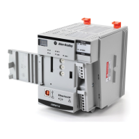
The following timing diagram shows the relationship between status bits and
instruction operation. When the instruction execution is complete, the .DN bit is
set.
If the rung-condition-in is true at completion, the .EN and .DN bit are set until
the rung-condition-in goes false. When the rung-condition-in goes false, these
bits are cleared and the .POS value is cleared.
If the rung-condition-in is false at completion, the .EN bit is cleared immediately.
One scan after the .EN bit is cleared, the .DN bit and the .POS value are cleared.
Incremental Mode
Incremental mode manipulates one element of the array each time the
instruction’s rung-condition-in goes from false to true.
Multiple Scans
Multiple Scans
Rung-condition-in
.EN Bit
.DN Bit
Scan Of The Instruction
Clears Status Bits And
clears .POS Value
Clears Status Bits And
clears .POS Value
Rung is True at Completion
Rung is False at Completion
40013
Operation Complete
Operation Complete
16643
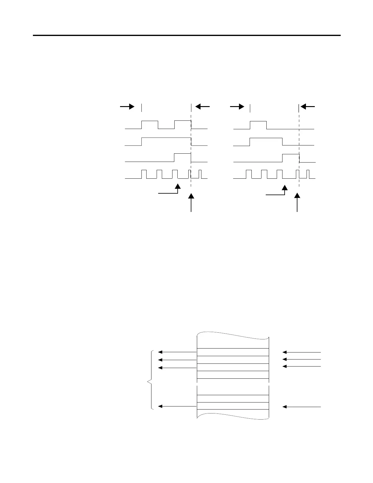
1st Instruction Enable
2nd Instruction Enable
3rd Instruction Enable
Last Instruction Enable
 Loading...


