190 Rockwell Automation Publication 1756-RM003N-EN-P - October 2011
Chapter 4 Input/Output Instructions (MSG, GSV, SSV, IOT)
For Block Transfers
For block transfer messages, add the following modules to the I/O configuration
of the controller.
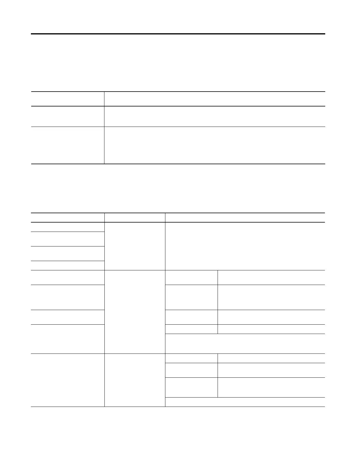
Specify a Communication Method or Module Address
Use the following table to select a communication method or module address for
the message.
For block-transfers over this
network
Add these modules to the I/O configuration
ControlNet
· Local communication module (for example, 1756-CNB module)
· Remote adapter module (for example, 1771-ACN module)
Universal remote I/O
· Local communication module (for example, 1756-DHRIO module)
· One emote adapter module (for example, 1771-ASB module) for each rack, or portion of a rack, in
the chassis
· Block-transfer module (optional)
If the destination device is Then select And specify
Logix5000 controller CIP No other specifications required.
PLC-5 controller over an EtherNet/IP
network
PLC-5 controller over a ControlNet
network
SLC 5/05 controller
PLC-5 controller over a DH+ network DH+ Channel Channel A or B of the 1756-DHRIO module that is
connected to the DH+ network.
SLC controller over a DH+ network Source Link Link ID assigned to the backplane of the controller in
the routing table of the 1756-DHRIO module. (The
source node in the routing table is automatically the
slot number of the controller.).
PLC-3 processor Destination Link Link ID of the remote DH+ link where the target device
resides.
PLC-2 processor Destination Node Station address of the target device, in octal.
If there is only one DH+ link and you did not use the RSLinx software to configure
the DH/RIO module for remote links, specify 0 for both the Source Link and the
Destination Link.
Application on a workstation that is
receiving an unsolicited message
routed over an EtherNet/IP or
ControlNet network through
RSLinx software
CIP with Source ID
(This lets the application
receive data from a
controller.)
Source Link Remote ID of the topic in RSLinx software.
Destination Link Virtual Link ID set up in RSLinx
software (0…65535).
Destination Node Destination ID (0…77 octal) provided by the
application to RSLinx. For a DDE topic in RSLinx
software, use 77.
The slot number of the ControlLogix controller is used as the Source Node.
 Loading...


