660 Rockwell Automation Publication 1756-RM003N-EN-P - October 2011
Appendix B Function Block Attributes
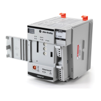
Resolve Data Flow Between Two Blocks
If you use two or more wires to connect two blocks, use the same data flow
indicators for all of the wires between the two blocks.
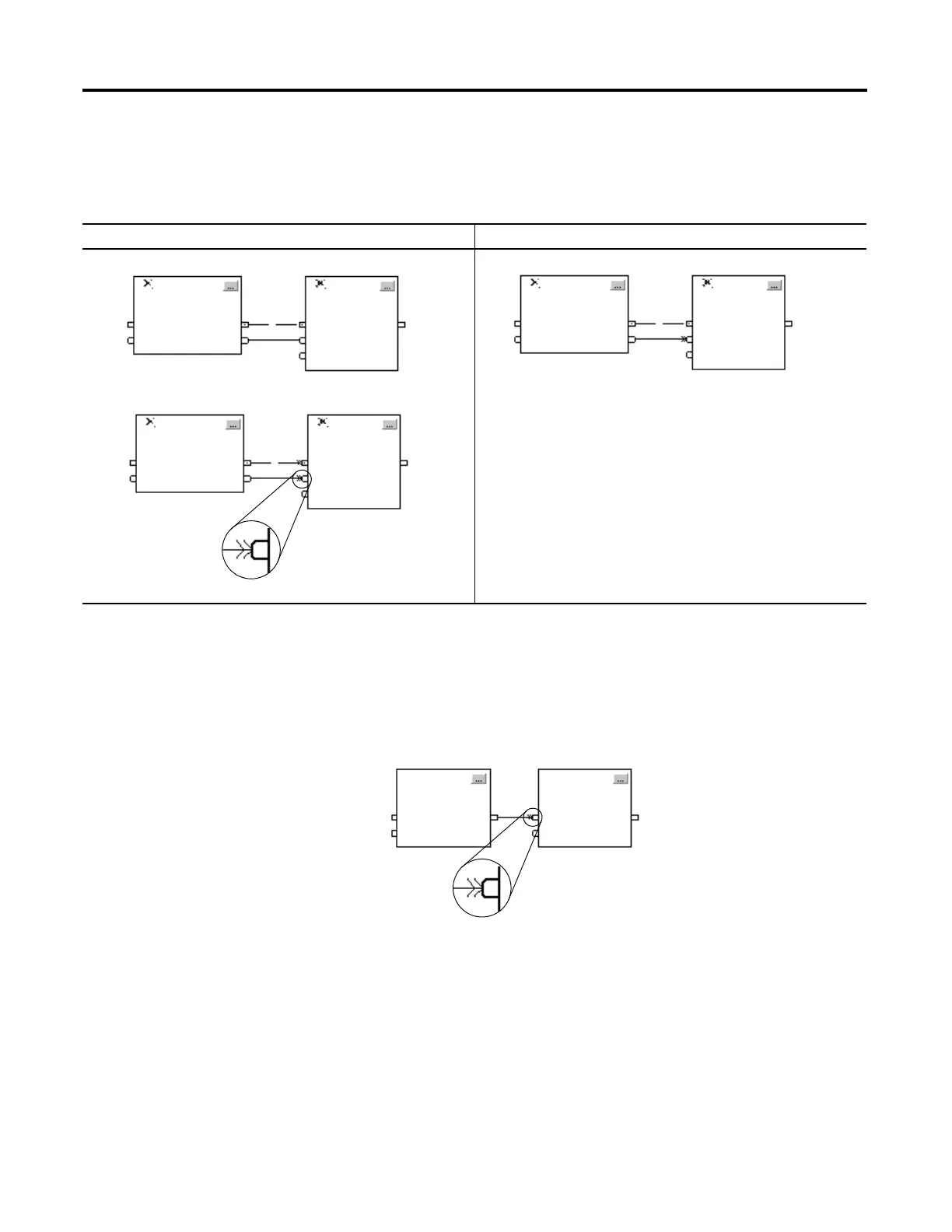
Create a One Scan Delay
To produce a one scan delay between blocks, use the Assume Data Available
indicator. In the following example, block 1 executes first. It uses the output from
block 2 that was produced in the previous scan of the routine.
Summary
A function block routine executes in this order.
1. The controller latches all data values in IREFs.
2. The controller executes the other function blocks in the order determined
by how they are wired.
3. The controller writes outputs in OREFs.
This is okay This is not okay
Neither wire uses the Assume Data Available indicator.
Both wires use the Assume Data Available indicator.
One wire uses the Assume Data Available indicator while the other wire
does not.
Assume Data Available
Indicator
21
Assume Data Available Indicator
 Loading...


