Rockwell Automation Publication 1756-RM003N-EN-P - October 2011 193
Input/Output Instructions (MSG, GSV, SSV, IOT) Chapter 4
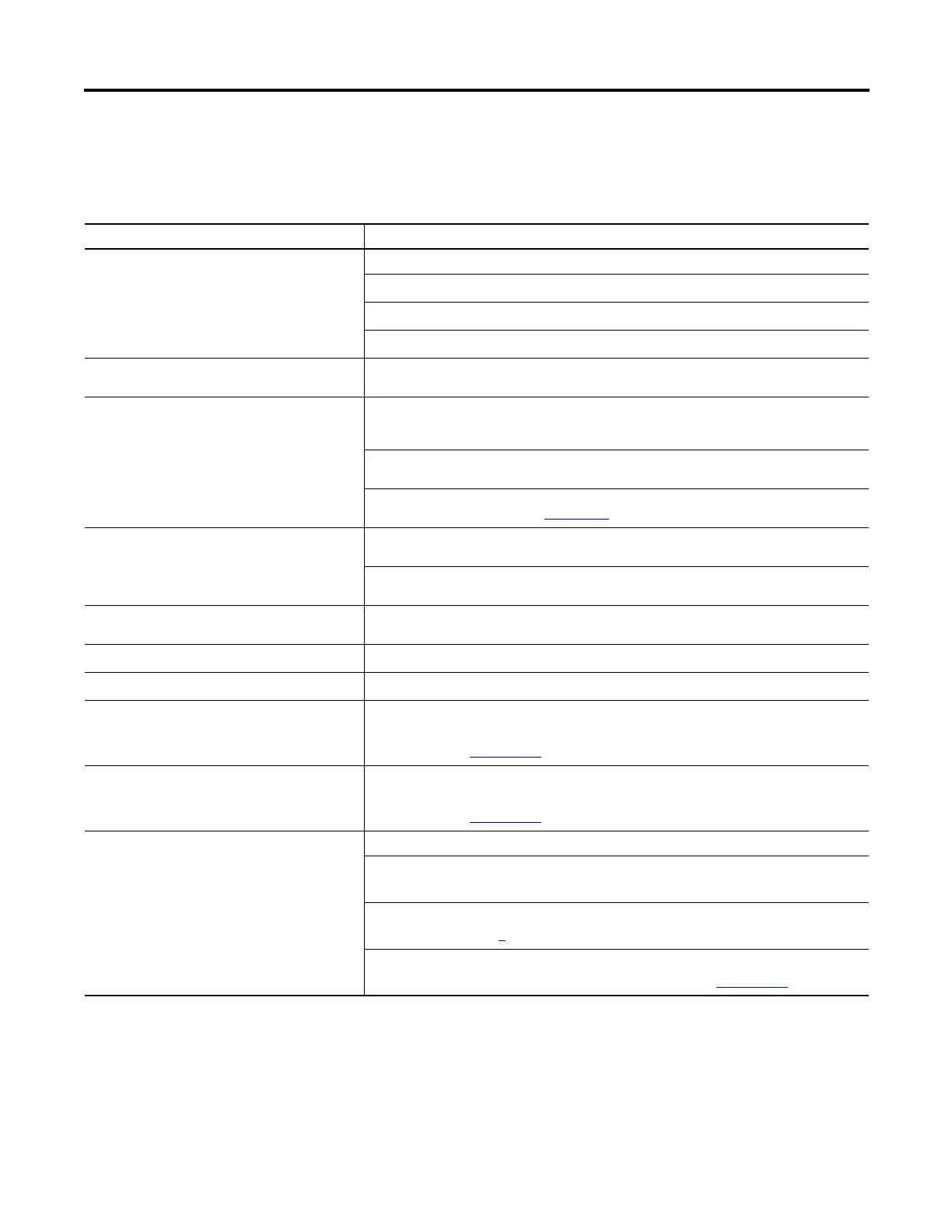
Guidelines
As you plan and program your MSG instructions, follow these guidelines.
Guideline Details
1. For each MSG instruction, create a control tag. Each MSG instruction requires its own control tag.
· Data type = MESSAGE
· Scope = controller
· The tag cannot be part of an array or a user-defined data type.
2. Keep the source and/or destination data at the
controller scope.
A MSG instruction can access only tags that are in the Controller Tags folder (controller scope).
3. If your MSG is to a device that uses 16-bit
integers, use a buffer of INTs in the MSG and
DINTs throughout the project.
If your message is to a device that uses 16-bit integers, such as a PLC-5® or SLC 500™ controller,
and it transfers integers (not REALs), use a buffer of INTs in the message and DINTs throughout
the project.
This increases the efficiency of your project because Logix controllers execute more efficiently
and use less memory when working with 32-bit integers (DINTs).
To convert between INTs and DINTs, see the Logix5000 Controllers Common Procedures
Programming Manual, publication 1756-PM001
.
4. Cache the connected MSGs that execute most
frequently.
Cache the connection for those MSG instructions that execute most frequently, up to the
maximum number permissible for your controller revision.
This optimizes execution time because the controller does not have to open a connection each
time the message executes.
5. If you want to enable more than 16 MSGs at one
time, use some type of management strategy.
If you enable more than 16 MSGs at one time, some MSG instructions may experience delays in
entering the queue. To guarantee the execution of each message, use one of these options:
· Enable each message in sequence.
· Enable the messages in groups.
· Program a message to communicate with multiple devices. For more information,
see the Logix5000 Controllers Common Procedures Programming Manual,
publication 1756-PM001
.
· Program logic to coordinate the execution of messages. For more information,
see the Logix5000 Controllers Common Procedures Programming Manual,
publication 1756-PM001
.
6. Keep the number of unconnected and uncached
MSGs less than the number of unconnected
buffers.
The controller can have 10…40 unconnected buffers. The default number is 10.
· If all the unconnected buffers are in use when an instruction leaves the message
queue, the instruction errors and does not transfer the data.
· You can increase the number of unconnected buffers (40 max), but continue to
follow guideline 5
.
· To increase the number of unconnected buffers, see the Logix5000 Controllers
Common Procedures Programming Manual, publication 1756-PM001
.

 Loading...


