Rockwell Automation Publication 2080-UM002G-EN-E - March 2015 141
Use the High-Speed Counter and Programmable Limit Switch Chapter 8
When the HSC is in Counting mode, and PLS is enabled, this parameter indi-
cates which PLS element is used for the current HSC configuration.
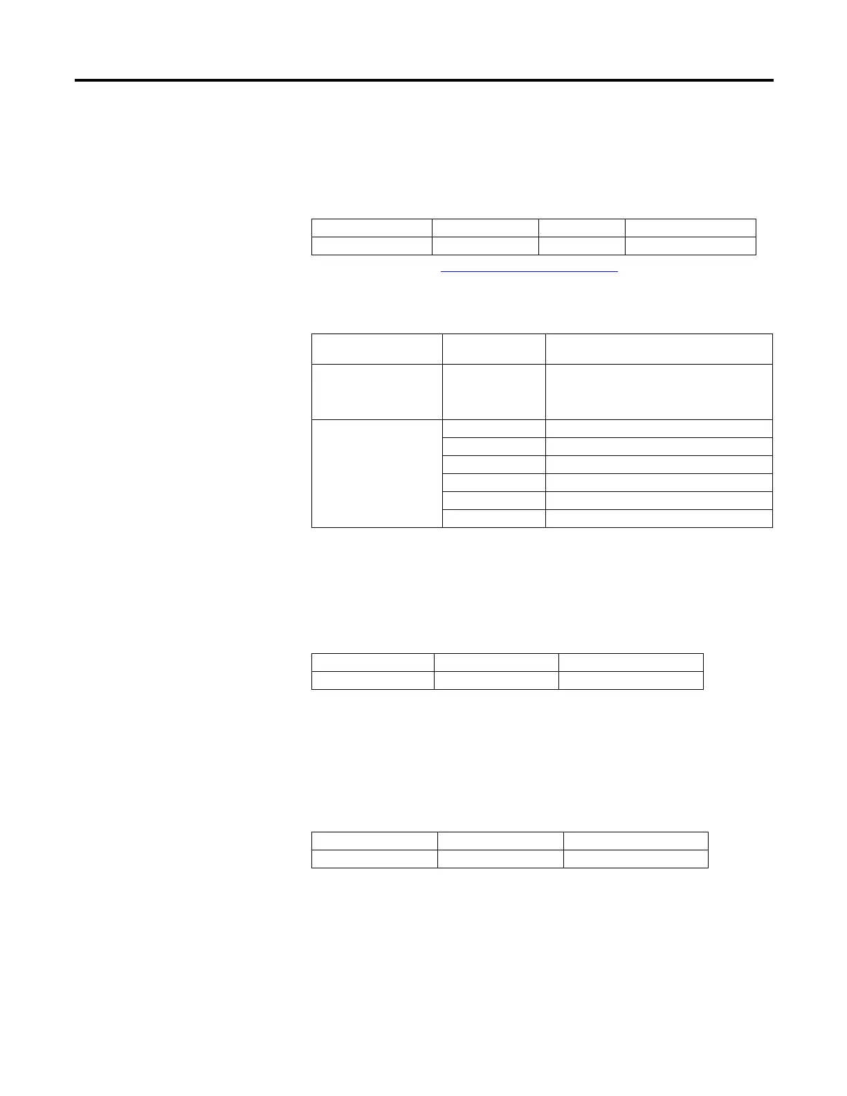
Error Code (HSCSTS.ErrorCode)
The Error Codes detected by the HSC sub-system are displayed in this word.
Errors include:
Writing to this element is not recommended except for clearing existing errors
and to capture new HSC errors.
Accumulator (HSCSTS.Accumulator)
HSCSTS.Accumulator contains the number of counts detected by the HSC
sub-system. If either mode 0 or mode 1 is configured, the accumulator is reset to 0
when a high preset is reached or when an overflow condition is detected.
High Preset (HSCSTS.HP)
The HSCSTS.HP is the upper setpoint (in counts) that defines when the HSC
sub-system generates an interrupt.
The data loaded into the high preset must be less than or equal to the data
resident in the overflow (HSCAPP.OFSetting) parameter or an HSC error is
generated.
Description Data Format HSC Modes
(1)
(1) For Mode descriptions, see HSC Mode (HSCAPP.HSCMode) on page 126.
User Program Access
HSCSTS.ErrorCode Word (INT) 0…9 read only
Error Code Sub-element HSC counting Error
Code
Error Description
Bit 15…8 (high byte) 0…255 The non-zero value for high byte indicates that
the HSC error is due to PLS data setting. The
value of high byte indicates which element of
PLS data triggers the error.
Bit 7-0 (low byte) 0x00 No error
0x01 Invalid HSC counting mode
0x02 Invalid High preset
0x03 Invalid overflow
0x04 Invalid underflow
0x05 No PLS data
Description Data Format User Program Access
HSCSTS.Accumulator long word (32-bit INT) read only
Description Data Format User Program Access
HSCSTS.HP long word (32-bit INT) read only

 Loading...


