Rockwell Automation Publication 2080-UM002G-EN-E - March 2015 187
Modbus Mapping for Micro800 Appendix B
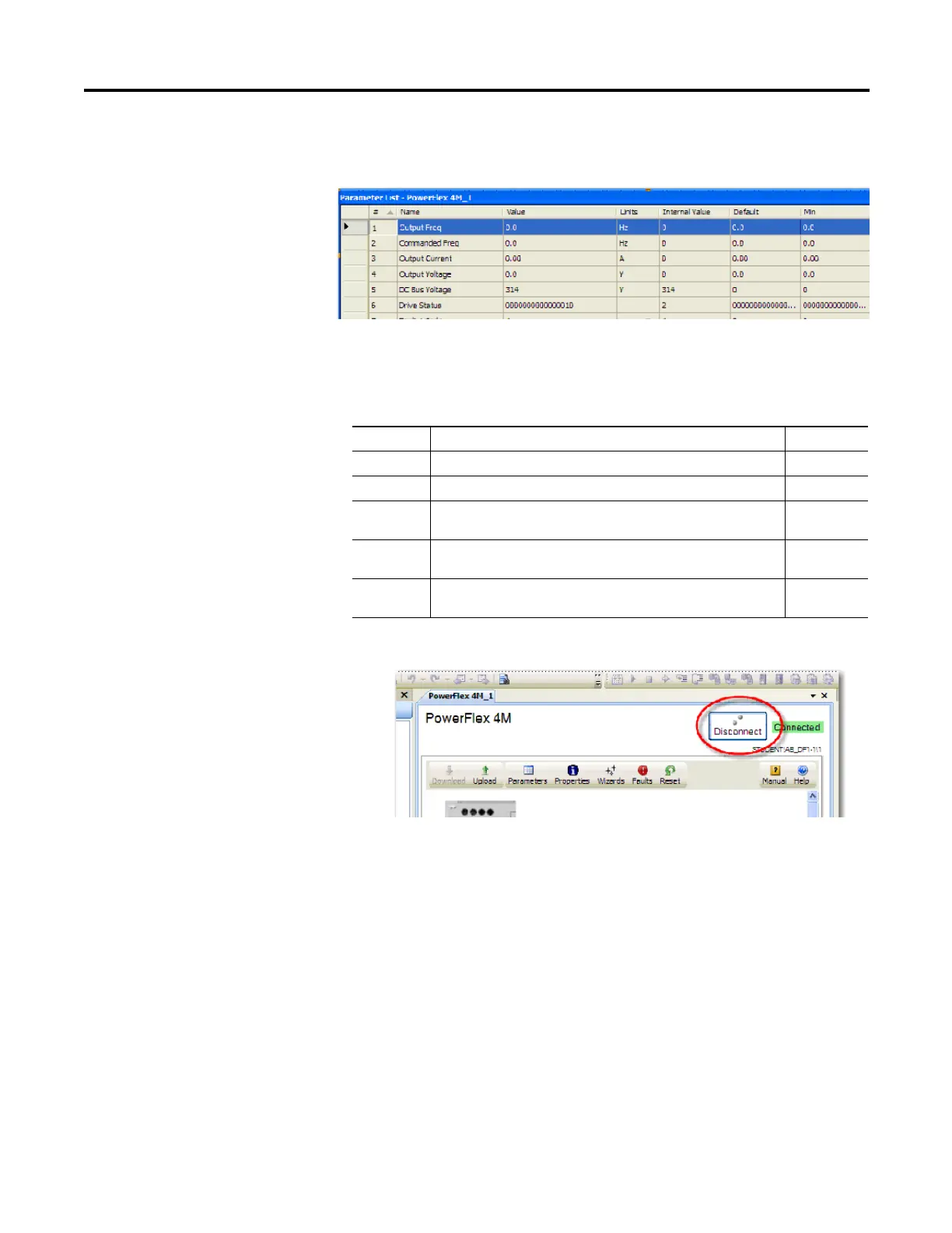
6. The Parameter window opens. Resize it to view the parameters. From this
window, you can view and set data values of Parameters.
7. From the Parameter window, change the following Parameters to set the
communications for Modbus RTU so that the PowerFlex 4M Drive will
communicate with Micro830/850 via Modbus RTU communication.
8. Disconnect the Communications and save your project.
9. Turn off the power to the drive until the PowerFlex 4M display blanks out
completely, then restore power to the PowerFlex 4M.
The drive is now ready to be controlled by Modbus RTU communication
commands initiated from the Micro830/850 controller.
Modbus devices can be 0-based (registers are numbered starting at 0), or 1-based
(registers are numbered starting at 1). When PowerFlex 4-Class drives are used
with Micro800 family controllers, the register addresses listed in the PowerFlex
User Manuals need to be offset by n+1.
For example, the Logic Command word is located at address 8192, but your
Micro800 program needs to use 8193 (8192+1) to access it.
Modbus Address (n+1 value shown)
8193 Logic Command word (Stop, Start, Jog, etc.)
Parameter Description Setting
C302 Comm. Data Rate (Baud Rate) 4 = 19200 bps 4
C303 Communication Node Address (address range is 1…127) 2
C304 Comm. Loss Action ( Action taken when loss communication) 0 =
Fault with coast stop
0
C305 Comm. Loss Time (Time remain in communication before taking
action set in C304) 5 sec ( Max. 60)
5
C306 Comm. Format (Data/Parity/Stop) RTU:8 Data Bit, Parity None, 1
Stop bit
0

 Loading...


