Home
Allen-Bradley
Controller
Micro830
Allen-Bradley Micro830 User Manual
5
of 1
of 1 rating
284 pages
Give review
Manual
Specs
To Next Page
To Next Page
To Previous Page
To Previous Page
Loading...
Rockwell Aut
omation Publ
ication 2080
-UM002G-
EN-E - Mar
ch 2015
57
Communication Connections
Chapter
5
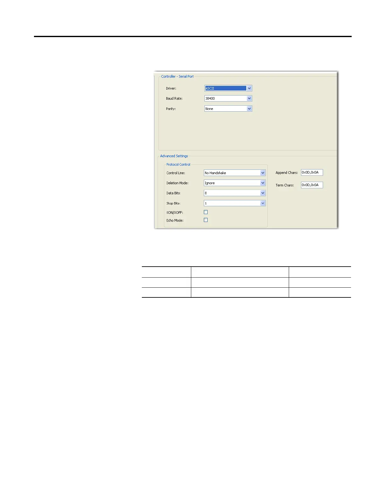
2.
Select AS
CII on the Driv
er field.
3.
Spe
ci
f
y
b
au
d r
ate
an
d
pa
ri
t
y
.
ASCII Param
eters
Parameter
Options
Default
Baud Rate
1200, 2400, 4800, 9600,
19200, 38400
1920
0
Parity
None, Odd, Even
None
70
72
Table of Contents
Default Chapter
3
Additional Resources
3
Preface
3
Purpose of this Manual
3
Who Should Use this Manual
3
Table of Contents
7
Chapter 1 Hardware Features
15
Hardware Overview
15
Micro830 Controllers
16
Micro850 Controllers
18
Programming Cables
20
Embedded Ethernet Support
21
Embedded Serial Port Cables
21
Chapter 2 Programming Software for Micro800 Controllers
23
Obtain Connected Components Workbench
23
Use Connected Components Workbench
23
Using Run Mode Change
23
About Your Controller
23
Uncommitted Changes
25
RMC Memory
25
Limitations of RMC
27
Agency Certifications
28
Compliance to European Union Directives
28
EMC Directive
28
Low Voltage Directive
28
Installation Considerations
29
Environment and Enclosure
30
Preventing Electrostatic Discharge
30
Safety Considerations
32
North American Hazardous Location Approval
32
Disconnecting Main Power
32
Safety Circuits
33
Power Distribution
33
Periodic Tests of Master Control Relay Circuit
33
Power Considerations
34
Isolation Transformers
34
Power Supply Inrush
34
Loss of Power Source
34
Input States on Power down
35
Other Types of Line Conditions
35
Preventing Excessive Heat
35
Master Control Relay
36
Using Emergency-Stop Switches
37
Schematic - Using IEC Symbols
38
Schematic - Using ANSI/CSA Symbols)
39
Chapter 3 Controller Mounting Dimensions
41
Mounting Dimensions
41
DIN Rail Mounting
43
Panel Mounting
44
Panel Mounting Dimensions
44
System Assembly
47
Install Your Controller
41
Chapter 4
49
Wire Your Controller
49
Wiring Requirements and Recommendation
49
Use Surge Suppressors
50
Recommended Surge Suppressors
52
Grounding the Controller
53
Wiring Diagrams
53
Controller I/O Wiring
56
Minimize Electrical Noise
57
Analog Channel Wiring Guidelines
57
Minimize Electrical Noise on Analog Channels
57
Grounding Your Analog Cable
58
Wiring Examples
58
Embedded Serial Port Wiring
59
Chapter 5
61
Communication Connections
61
Overview
61
Supported Communication Protocols
61
Modbus RTU
62
Modbus/Tcp Client/Server
62
CIP Symbolic Client/Server
63
CIP Client Messaging
64
Ascii
64
CIP Communications Pass-Thru
64
Examples of Supported Architectures
65
Configure Serial Port
66
Configure CIP Serial Driver
67
Configure Modbus RTU
69
Configure ASCII
70
Use Modems with Micro800 Controllers
66
Making a DF1 Point-To-Point Connection
66
Construct Your Own Modem Cable
66
Configure Ethernet Settings
72
Ethernet Host Name
74
Configure CIP Serial Driver
74
OPC Support Using Rslinx Enterprise
74
Chapter 6 Overview of Program Execution
75
Program Execution in Micro800
75
Rockwell Automation Publication 2080-UM002G-EN-E - March
75
Controller Load and Performance Considerations
76
Periodic Execution of Programs
77
Execution Rules
76
Power up and First Scan
77
Variable Retention
78
Guidelines and Limitations for Advanced Users
78
Memory Allocation
78
Chapter 7 Use the Micro800 Motion Control Feature
82
Motion Control
82
Input and Output Signals
84
Motion Control Function Blocks
87
General Rules for the Motion Control Function Blocks
89
Motion Axis and Parameters
97
Motion Axis State Diagram
98
Axis States
99
Limits
100
Motion Stop
102
Motion Direction
103
Axis Elements and Data Types
104
Axis Error Scenarios
105
Mc_Engine_Diag Data Type
106
Function Block and Axis Status Error Codes
106
Major Fault Handling
109
Motion Axis Configuration in Connected Components Workbench
109
Add New Axis
110
Edit Axis Configuration
111
Axis Start/Stop Velocity
118
Real Data Resolution
118
PTO Pulse Accuracy
120
Motion Axis Parameter Validation
121
Delete an Axis
121
Monitor an Axis
121
Homing Function Block
122
Conditions for Successful Homing
123
Mc_Home_Abs_Switch
123
Mc_Home_Limit_Switch
125
Mc_Home_Ref_With_Abs
126
Mc_Home_Ref_Pulse
128
Mc_Home_Direct
129
Use PTO for PWM Control
130
POU Pwm_Program
131
HSC Feedback Axis
132
Chapter 8
133
High-Speed Counter Overview
133
Programmable Limit Switch Overview
133
Use the High-Speed Counter and Programmable Limit Switch
133
What Is High-Speed Counter
134
Features and Operation
134
HSC Inputs and Wiring Mapping
135
High Speed Counter (HSC) Data Structures
139
HSC APP Data Structure
139
PLS Enable (Hscapp.plsenable)
139
Hscid (Hscapp.hscid)
140
HSC Mode (Hscapp.hscmode)
140
Accumulator (HSCAPP. Accumulator)
146
High Preset (Hscapp.hpsetting)
146
Low Preset (Hscapp.lpsetting)
147
Overflow Setting (Hscapp.ofsetting)
147
Underflow Setting (Hscapp.ufsetting)
147
Output Mask Bits (Hscapp.outputmask)
148
High Preset Output (Hscapp.hpoutput)
149
Low Preset Output (Hscapp.lpoutput)
149
HSC STS (HSC Status) Data Structure
150
Counting Enabled (Hscsts.countenable)
150
Error Detected (Hscsts.errordetected)
150
Count up (Hscsts.countupflag)
151
Count down (Hscsts.countdownflag)
151
Mode Done (Hscsts.mode1Done)
151
Overflow (HSCSTS.OVF)
151
Underflow (HSCSTS.UNF)
152
Count Direction (Hscsts.countdir)
152
High Preset Reached (Hscsts.hpreached)
152
Low Preset Reached (Hscsts.lpreached)
153
Overflow Interrupt (Hscsts.ofcauseinter)
153
Underflow Interrupt (Hscsts.ufcauseinter)
153
High Preset Interrupt (Hscsts.hpcauseinter)
154
Low Preset Interrupt (Hscsts.lpcauseinter)
154
Programmable Limit Switch Position (Hscsts.plsposition)
154
Error Code (Hscsts.errorcode)
155
Accumulator (Hscsts.accumulator)
155
High Preset (HSCSTS.HP)
155
Low Preset (HSCSTS.LP)
156
High Preset Output (Hscsts.hpoutput)
156
Low Preset Output (Hscsts.lpoutput)
156
HSC (High Speed Counter) Function Block
157
HSC Commands (Hsccmd)
157
HSC_SET_STS Function Block
159
Programmable Limit Switch (PLS) Function
159
PLS Data Structure
160
PLS Operation
160
PLS Example
161
HSC Interrupts
162
HSC Interrupt Configuration
163
HSC Interrupt POU
164
Auto Start (HSC0.AS)
164
Mask for IV (HSC0.MV)
164
Mask for in (HSC0.MN)
164
Mask for IH (HSC0.MH)
165
Mask for IL (HSC0.ML)
165
HSC Interrupt Status Information
165
User Interrupt Enable (Hsc0.Enabled)
165
User Interrupt Executing (HSC0.EX)
165
User Interrupt Pending (HSC0.PE)
166
User Interrupt Lost (HSC0.LS)
166
Use HSC
166
Chapter 9 Controller Security
167
Compatibility
167
Controller Security
167
Exclusive Access
167
Password Protection
167
Work with a Locked Controller
168
Upload from a Password-Protected Controller
168
Debug a Password-Protected Controller
169
Download to a Password-Protected Controller
169
Transfer Controller Program and Password-Protect Receiving
169
Controller
169
Back up a Password-Protected Controller
170
Configure Controller Password
170
Recover from a Lost Password
170
Appendix A Micro830 Controllers
171
Micro830 10-Point Controllers
171
Micro830 16-Point Controllers
175
Micro830 24-Point Controllers
178
Micro830 48-Point Controllers
182
Micro830 and Micro850 Relay Charts
187
Specifications
171
Micro850 Controllers
187
Micro850 24-Point Controllers
188
Micro850 48-Point Controllers
191
Micro800 Programmable Controller External AC Power Supply
195
Appendix B Modbus Mapping
197
Endian Configuration
197
Mapping Address Space and Supported Data Types
197
Example 1, Panelview Component HMI (Master) to Micro800
198
(Slave)
198
Example 2, Micro800 (Master) to Powerflex 4M Drive (Slave)
199
Performance
202
Modbus Mapping for Micro800
197
Flash Upgrade Your Micro800 Firmware
203
Controller through USB
208
Establish Communications between Rslinx and a Micro830/Micro850
208
Configure Controller Password
214
Set Controller Password
215
Change Password
216
Clear Password
217
Use the High Speed Counter
218
Create the HSC Project and Variables
220
Assign Values to the HSC Variables
223
Assign Variables to the Function Block
226
Run the High Speed Counter
227
Use the Programmable Limit Switch (PLS) Function
229
Forcing I/Os
231
Checking if Forces (Locks) Are Enabled
231
I/O Forces after a Power Cycle
232
Using Run Mode Change
233
Create the Project
233
Edit the Project Using Run Mode Change
236
Appendix C
203
Appendix D Information about Using Interrupts
241
What Is an Interrupt
241
When Can the Controller Operation be Interrupted
242
Priority of User Interrupts
242
User Interrupt Configuration
244
User Fault Routine
244
User Interrupts
241
User Interrupt Instructions
245
STIS - Selectable Timed Start
245
UID - User Interrupt Disable
246
UIE - User Interrupt Enable
248
UIF - User Interrupt Flush
249
UIC - User Interrupt Clear
250
Selectable Time Interrupt (STI) Function Configuration and Status
251
STI Function Configuration
252
STI Function Status Information
252
Rockwell Automation Publication 2080-UM002G-EN-E - March
252
Using the Selectable Timed Interrupt (STI) Function
251
Using the Event Input Interrupt (EII) Function
253
Event Input Interrupt (EII) Function Configuration and Status
254
EII Function Configuration
254
EII Function Status Information
255
Appendix E Status Indicators on the Controller
257
Error Conditions
258
Normal Operation
258
Error Codes
259
Controller Error Recovery Model
266
Calling Rockwell Automation for Assistance
267
Appendix F
270
How to Autotune
271
How Autotune Works
272
Troubleshooting an Autotune Process
273
PID Application Example
274
PID Code Sample
275
Appendix G
277
Calculate Total Power for Your Micro830/Micro850 Controller
277
Other manuals for Allen-Bradley Micro830
Manual
354 pages
5
Based on 1 rating
Ask a question
Give review
Questions and Answers:
Need help?
Do you have a question about the Allen-Bradley Micro830 and is the answer not in the manual?
Ask a question
Allen-Bradley Micro830 Specifications
General
Brand
Allen-Bradley
Model
Micro830
Category
Controller
Language
English
Related product manuals
Allen-Bradley Micro800
78 pages
Allen-Bradley Micro820
184 pages
Allen-Bradley Micro850
24 pages
Allen-Bradley Micro810
102 pages
Allen-Bradley Micro870
354 pages
Allen-Bradley MicroLogix 1100
256 pages
Allen-Bradley micrologix 1500
174 pages
Allen-Bradley MicroLogix 1400
694 pages
Allen-Bradley MicroLogix 1000
422 pages
MicroLogix 1000 PLC
2 pages
Allen-Bradley 1756-M08SE
236 pages
Allen-Bradley PowerFlex 525
244 pages

 Loading...


