Behavior models used in CIP Motion
52 Rockwell Automation Publication MOTION-RM003I-EN-P - February 2018
4. Start Inhibited
5. Stopped
See also
State Behavior on page 61
Fault and Alarm Behavior on page 41
Exceptions on page 41
The current state of the Motion Control Axis Object instance is indicated by the
CIP Axis State attribute. State transitions can be initiated either directly using the
Axis Control request mechanism or by conditions that occur in either the
controller or motion device during operation.
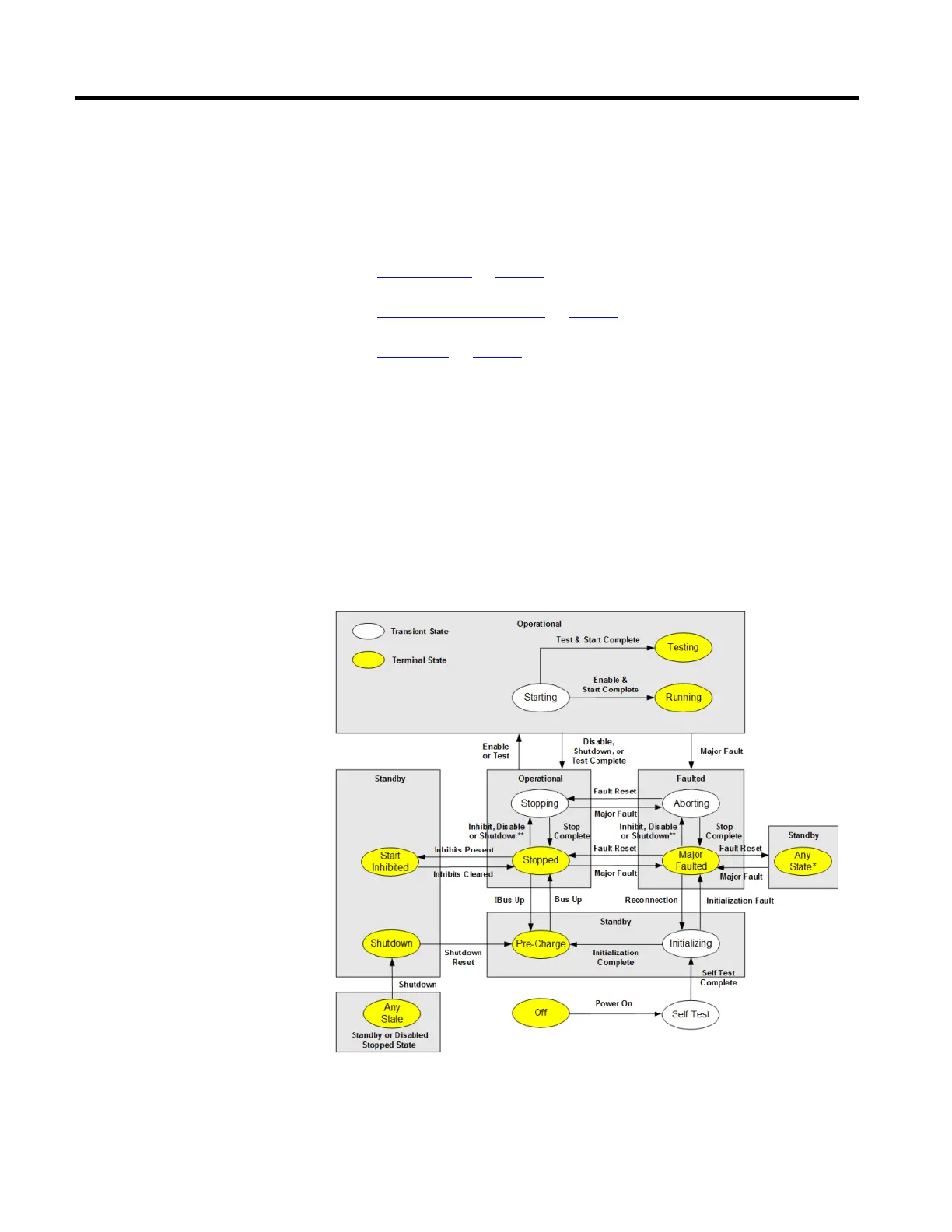
The following diagram illustrates the basic operating states of the Motion Control
Axis when actively controlling axis motion (Control Mode != No Control).
Shaded regions show mapping of Axis States to corresponding Identity Object
states. State transitions terminating on shaded boxes can transition to any axis
state within the box.
Active Control Axis Behavior
Model

 Loading...


