Behavior models used in CIP Motion
72 Rockwell Automation Publication MOTION-RM003I-EN-P - February 2018
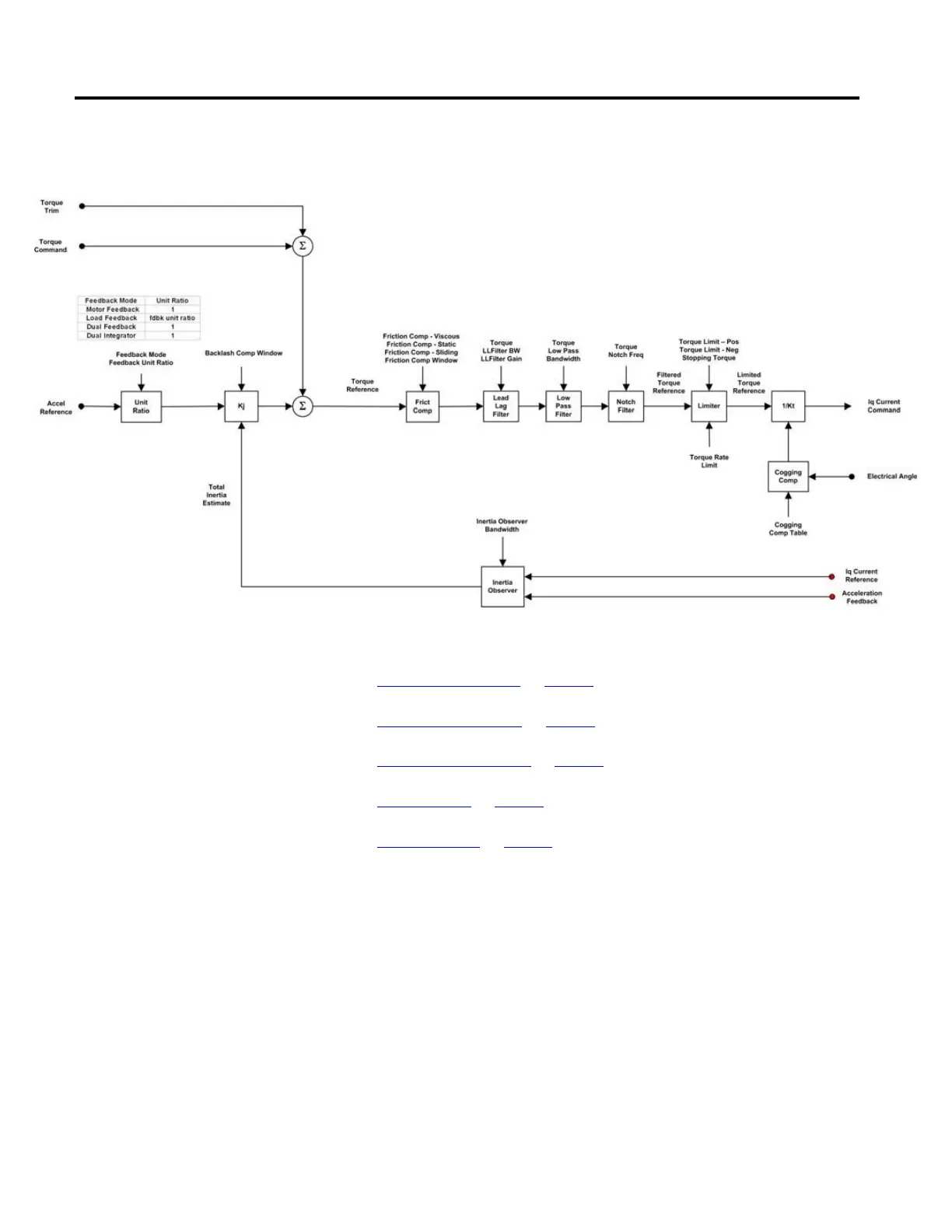
The following diagram provides an overview of the torque control behavior
model:
See also
Torque Input Sources on page 72
Inertia Compensation on page 73
Friction Compensation on page 75
Torque Filters on page 77
Torque Limiter on page 78
The Torque Control model can take input from a variety of sources depending on
the Control Mode. Input to the Torque Reference path can come through the
cyclic Torque Command or Torque Trim signal in Torque Control mode. In
Position or Velocity Control mode, torque input is derived from the outer velocity
loop or acceleration loop by bringing in the resulting acceleration signals and
scaling these signals into equivalent torque.
Acceleration to Torque Scaling
Because the acceleration input signals into the Torque Control section are
expressed in units of acceleration, a scaling factor, Kj, is needed to convert
acceleration units to torque % Rated Torque units. This scaling factor, when
properly configured, represents the total System Inertia or mass of the system that

 Loading...


