Behavior models used in CIP Motion
Rockwell Automation Publication MOTION-RM003I-EN-P - February 2018 59
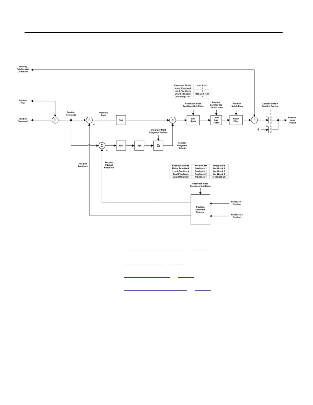
The following diagram provides an overview of the closed loop position control
behavior model.
See also
Position Feedback Selection on page 59
Position PI Gains on page 60
Velocity Feedforward on page 60
Position Loop Output Filters on page 61
Feedback to the PI regulator can be derived from two different feedback channels.
This flexibility allows the position loop to operate with either a motor based
feedback device that is typically attached to the Feedback 1 channel or a load-side
feedback device that is connected to the Feedback 2 channel. Which feedback
source is used by the loop is governed by the Feedback Mode attribute.
When the Feedback Mode calls for Dual Feedback operation, the position loop
utilizes the Feedback 2 channel and the velocity loop uses the Feedback 1 channel.
Since the two feedback channels may not have the same feedback resolution, it is
necessary to convert position loop output from Feedback 1 units to Feedback 2
Position Feedback Selection

 Loading...


