68 Rockwell Automation Publication 20A-UM001N-EN-P - July 2013
Chapter 1 Programming and Parameters
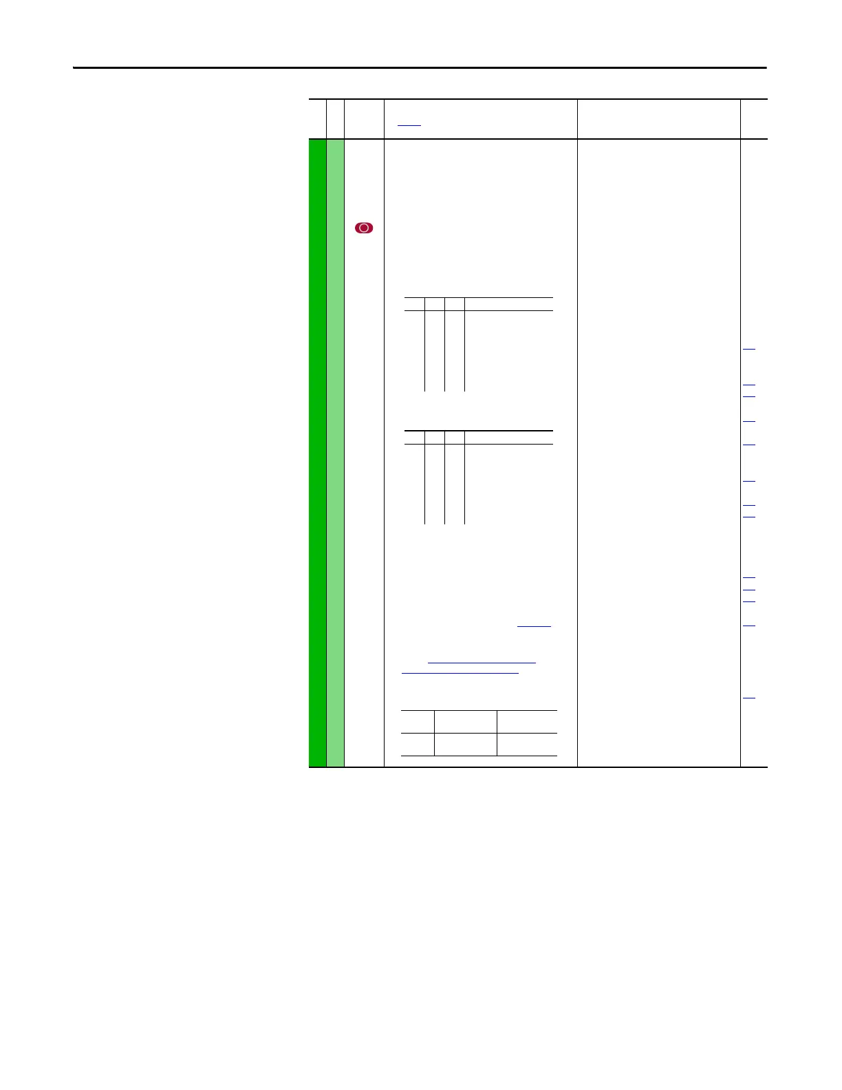
INPUTS and OUTPUTS (file J)
Digital Inputs
361
362
363
364
365
366
[Digital In1 Sel]
[Digital In2 Sel]
[Digital In3 Sel]
[Digital In4 Sel]
[Digital In5 Sel]
[Digital In6 Sel](7)
Selects the function for the digital inputs.
Important: Digital inputs are not designed to
work with a pulsed source.
(1)
When [Digital Inx Sel] is set to option 2 “Clear Faults”
the Stop button cannot be used to clear a fault
condition.
To access Preset Speed 1, set [Speed Ref A Sel] or
[Speed Ref B Sel] to “Preset Speed 1”.
(4)
Only Enhanced Control Drives.
(5)
Enhanced firmware revision V2.001 and later.
(6)
Opening an “Enable” input causes the motor to coast-
to-stop, ignoring any programmed Stop modes.
(7)
A dedicated hardware enable input is available via a
jumper selection. Refer to I/O Wiring Examples in the
PowerFlex 70 Adjustable Frequency AC Drive
Installation Instructions, publication 20A-IN009.
(8)
Configures the input to command a transition between
the Manual/Auto or Auto/Manual speed references.
Refer to “Auto” Speed Sources on page 116 and
“Manual” Speed Sources on page117 for details.
“Manual/Auto” (68) is similar to “Auto/Manual” (18)
except that the polarity is opposite.
Default:
Default:
Default:
Default:
Default:
Default:
Options:
4
5
18
15
16
17
0
1
2
3
4
5
6
7
8
9
10
11
12
13
14
15…17
18
19
20
21
22
23
24
25
26
27
28
29
30
31…33
34
35
36…40
41, 42
43
44
45
46
47…57
58
59
60
“Stop – CF”
(1)
“Start”
“Auto/ Manual”
“Speed Sel 1”
“Speed Sel 2”
“Speed Sel 3”
“Not Used”
“Enable”
(6)
“Clear Faults”
(1)
“Aux Fault”
“Stop – CF”
(1)
“Start”
(9)(11)
“Fwd/ Reverse”
(9)
“Run”
(10)
“Run Forward”
(10)
“Run Reverse”
(10)
“Jo g”
(9)
“Jog1”
(4)
“Jog Forward”
“Jog Reverse”
“Stop Mode B”
“Bus Reg Md B”
“Speed Sel 1-3”
(2)
“Auto/ Manual”
(8)
“Local”
“Acc2 and Dec2”
“Accel 2”
“Decel 2”
“MOP Inc”
(12)
“MOP Dec”
(12)
“Excl Link”
(12)
“PI Enable”
“PI Hold”
“PI Reset”
“Reserved”
“Precharge En”
(4)(12)
“Spd/Trq Sel1-3”
(3)(13)
“Jog 2”
(4)
“PI Invert”
(4)
“Reserved”
“UserSet Sel1-2”
(5)
“Run Level”
(5)(12)
“RunFwd Level”
(5)(12)
“RunRev Level”
(5)(12)
“Run w/Comm”
(5)(12)
“Reserved”
“Sync Enable”
(13)
“Traverse Ena”
(13)
“Manual/Auto”
(8)(14)
100
156
162
096
140
194
380
125
088
108
124
205
620
File J
Group
No.
Parameter Name and Description
See page 14 for symbol descriptions
Values
Related
(2)
321<– “Speed Sel 1…3”
0
0
0
0
1
1
1
1
0
0
1
1
0
0
1
1
0
1
0
1
0
1
0
1
Reference A - P90
Reference B - P93
Preset Speed 2 - P102
Preset Speed 3 - P103
Preset Speed 4 - P104
Preset Speed 5 - P105
Preset Speed 6 - P106
Preset Speed 7 - P107
(3)
3 2 1 <– “Spd/Trq Sel1…3”
0
0
0
0
1
1
1
1
0
0
1
1
0
0
1
1
0
1
0
1
0
1
0
1
Zero Torque
Spd Reg
Torque Reg
Min Spd/Trq
Max Spd/Trq
Sum Spd/Trq
Absolute
Zero Trq
Input
State
“A ut o/ M an ua l ”
(18)
“Manual/Auto”
(68)
Lo
Hi
Auto
Manual
Manual
Auto

 Loading...


