42 Rockwell Automation Publication 20A-UM001N-EN-P - July 2013
Chapter 1 Programming and Parameters
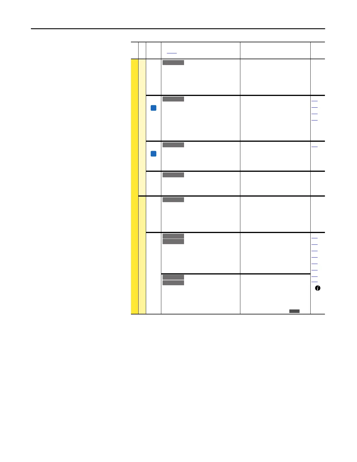
DYNAMIC CONTROL (file D)
Load Limits
152 [Droop RPM @ FLA]
Selects amount of droop that the speed
reference is reduced when at full load torque.
Zero disables the droop function.
Setting parameter 080 to 0 is recommended
when you are using the Droop function.
Default:
Min/Max:
Units:
0.0 rpm
0.0/200.0 rpm
0.1 rpm
153 [Regen Power Lim]
Sets the maximum power limit transfer from
the motor to the DC bus. When you are using an
external dynamic brake, set this parameter to its
minimum
(–800.0%) value. Overvoltage trips can occur if
set too negative and the connected brake is
unable to dissipate the energy.
Default:
Min/Max:
Units:
–50.0%
–800.0/0.0%
0.1%
053
161
162
163
154 [Current Rate Lim]
Sets the largest rate of change for the current
reference signal. This number is scaled in
percent of maximum motor current every 250
microseconds.
Default:
Min/Max:
Units:
400.0%
1.0/800.0%
0.1%
053
189 [Shear Pin Time]
Sets the time that the drive is at or above
current limit before a fault occurs. Zero disables
this feature.
Default:
Min/Max:
Units:
0.0 Secs
0.0/30.0 Secs
0.1 Secs
Stop/Brake Modes
145 [DB While Stopped]
Enables/disables dynamic brake operation.
Disabled = DB operates only when the drive is
running.
Enable = DB operates whenever the drive is
energized.
Default:
Options:
0
0
1
“Disabled”
“Disabled”
“Enabled”
155
156
[Stop Mode A]
[Stop Mode B]
Active stop mode. [Stop Mode A] is active unless
[Stop Mode B] is selected by digital inputs
programmed for “Stop Mode B.”
(1)
When you are using options 1 or 2, refer to
the Attention statements at [DC Brake Level].
Default:
Default:
Options:
1
0
0
1
2
3
“Ramp”
“Coast”
“Coast”
“Ramp”
(1)
“Ramp to Hold”
(1)
“DC Brake”
157
158
159
161
163
168
361…
366
[Stop/Brk Mode A]
[Stop/Brk Mode B]
See description above.
Default:
Default:
Options:
1
0
0
1
2
3
4
“Ramp”
“Coast”
“Coast”
“Ramp”
(1)
“Ramp to Hold”
(1)
“DC Brake”
“Fast Brake”
File D
Group
No.
Parameter Name and Description
See page 14 for symbol descriptions
Values
Related

 Loading...


