114 Rockwell Automation Publication 7000-UM202D-EN-P - May 2018
Chapter 2 Power Component Definition and Maintenance
The product uses the following fiber optic cable lengths.
There is one duplex fiber optic for each thyristor, which manages gating and
diagnostic functions. The circuitry on the respective driver boards determines
the functional status of the thyristor, and sends this information to the main
processor via a fail-safe light signal in the fiber optic. The main processor
initiates the firing command for the thyristor and transmits the signal to the
appropriate gate driver board via the gating fiber optic.
The color codes of the connectors are:
BLACK or GREY – is the transmitting end of the fiber optic.
BLUE – is the receiving end of the fiber optic.
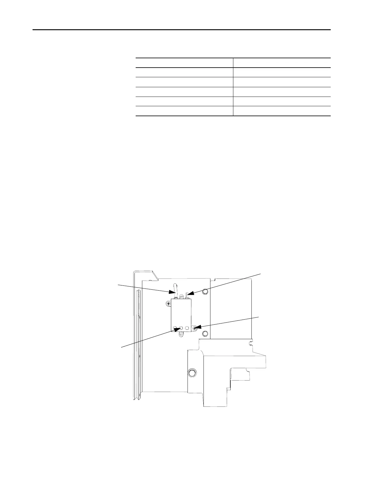
Air Pressure Sensor
An air pressure sensor is located in the converter cabinet. The sensor is located
in the upper left area near the uppermost inverter module.
Figure 99 - Air Pressure Sensor
The air pressure sensor measures the difference in air pressure between the
front and rear of the converter modules. The sensor sends a small direct current
voltage signal to the control circuits.
Duplex Simplex
5.0 m 5.0 m
5.5 m 6.0 m
6.0 m 10.0 m
6.5 m
7.0 m
Wire terminals
Flexible tube for low
pressure port
High pressure port
Mounting screw

 Loading...


