EasyManua.ls Logo

Allen-Bradley PowerFlex 7000 User Manual

Allen-Bradley PowerFlex 7000
218 pages
To Next Page IconTo Next Page
To Previous Page IconTo Previous Page
Page #87 background image
Rockwell Automation Publication 7000-UM202D-EN-P - May 2018 87
Power Component Definition and Maintenance Chapter 2
SCR Gate-to-Cathode Resistance
One test that can be performed on SCRs that cannot be performed on SGCTs
is a Gate-to-Cathode Resistance Test. Performing a Gate-to- Cathode
resistance measurement will identify damage to an SCR by revealing either an
open or shorted gate to cathode connection. To test an SCR from gate-to-
cathode, disconnect the SCR gate leads from the self powered gate driver board
and measure the gate-to-cathode resistance on the SCR firing card Phoenix
connector.
Figure 77 - SCR Gate-to-Cathode Test
The resistance value from gate-to-cathode should be between 10…20 Ω. A
value close to 0 Ω indicates that there is an internal short in the SCR. An
extremely high value indicates that the gate connection in the device has
broken.
If a Gate-to-Cathode test reveals a damaged SCR, see page 90
for the SCR
replacement procedure.
Test points for Gate-to-Cathode
Disconnect SCR
Phoenix
connector from
board

Table of Contents

Question and Answer IconNeed help?

Do you have a question about the Allen-Bradley PowerFlex 7000 and is the answer not in the manual?

Allen-Bradley PowerFlex 7000 Specifications

General IconGeneral
BrandAllen-Bradley
ModelPowerFlex 7000
CategoryController
LanguageEnglish

Summary

PowerFlex 7000 Medium Voltage AC Drive Air-Cooled (“B” Frame)—ForGe Control

Important User Information

General Precautions and Safety Warnings

Details ESD sensitivity, application errors, and personnel safety guidelines.

Preface

Manual Purpose and Audience

Outlines the manual's intent, intended users, and scope of coverage.

Chapter 1 PowerFlex 7000 Drive Overview

Drive Topology and Rectifier Configurations

Explains the drive's PWM-CSI topology and available rectifier designs.

Chapter 2 Power Component Definition and Maintenance

Control Power Off Tests and Interlocking

Outlines safety checks before applying control power and system interlocking mechanisms.

Voltage-Sensing Assembly and Replacement

Describes the voltage-sensing assembly and provides steps for its replacement.

Chapter 3 Control Component Definition and Maintenance

Control Power Components and Configurations

Details control power distribution for different drive configurations and ride-through capabilities.

AC/DC Power Supply Overview and Replacement

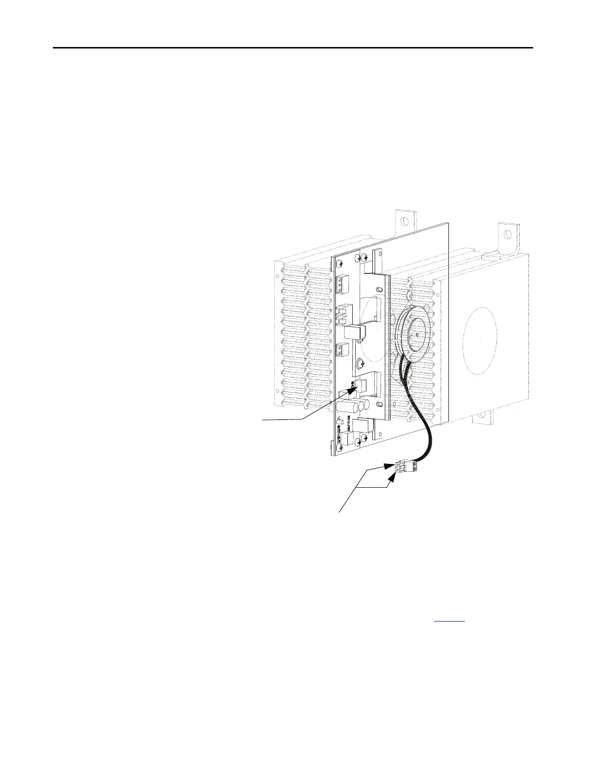
Covers AC/DC power supply functions, calibration, replacement, and diode replacement.

Appendix A Specifications

“B” Frame Drive Specifications

Lists general design specifications, including voltage, current, and enclosure details.

Appendix C Preventative Maintenance Schedule

Preventative Maintenance Overview

Categorizes maintenance into operational and annual tasks with key information requirements.

Appendix H Encoder Use and Torque Capabilities

Encoder Selection and Usage Guidelines

Provides guidance on when to use encoders and how to select them for optimal performance.

PowerFlex 7000 Drive Torque Capabilities

Details drive torque capabilities with and without encoders, and under different HPTC modes.

Related product manuals