Rockwell Automation Publication 7000-UM202D-EN-P - May 2018 19
PowerFlex 7000 Drive Overview Chapter 1
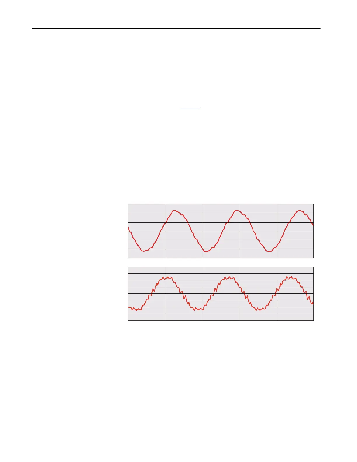
Motor Compatibility
The PowerFlex 7000 drive achieves near-sinusoidal current and voltage
waveforms to the motor, resulting in no significant additional heating or
insulation stress. Temperature rise in the motor connected to the VFD is
typically 3 °C (5.5 °F) higher compared to across-the-line operation. Voltage
waveform has dv/dt of less than 50 V/
µs. The peak voltage across the motor
insulation is the rated motor RMS voltage divided by 0.707.
Reflected wave and dv/dt issues often associated with VSI drives are a non-
issue with the drive. Figure 5
shows typical motor waveforms. The drive uses a
SHE pattern in the inverter to eliminate major order harmonics, plus a small
output capacitor (integral to the drive) to eliminate harmonics at higher
speeds.
Standard motors are compatible without de-rating, even on retrofit
applications.
Motor cable distance is virtually unlimited. Rockwell Automation has tested
this technology for controlling motors up to 15 km (9.3 mi) away from the
drive.
Figure 5 - Motor Waveforms at Full Load, Full Speed
300.00
200.00
100.00
0.00
-100.00
-200.00
-300.00
10.00K
7.50K
5.00K
2.50K
0.00K
-2.50K
-5.00K
-7.50K
-10.00K
100.00
110.00
120.00 130.00
TIME (ms)
Arms

 Loading...


