38 Rockwell Automation Publication 7000-UM202D-EN-P - May 2018
Chapter 2 Power Component Definition and Maintenance
Replacing the Voltage-Sensing Circuit Board Assembly
The number of sensing boards is dependent upon the drive rectifier
configuration. To access the sensing boards in an arc resistant drive, remove the
barriers behind the swing out LV compartment.
1. Verify there is no power to the equipment.
2. Mark the position of the ribbon cables and wires.
3. Remove the screws and lift the ring lugs from the terminals to remove
the wires.
4. Release the locking mechanism located on each side of the ribbon cable
connector and pull the ribbon cable straight out to prevent bending the
pins.
5. Remove the four nuts and washers that secure the assembly to the studs
welded to the frame.
6. Remove the old VSB and replace with the new VSB on the studs, using
the existing hardware to secure the assembly. Do not over-torque the
connections or you may break the studs.
7. Replace ring lugs on terminals. Plug in ribbon cables making sure that
cables are positioned properly and fitting is secure (locking mechanism
is engaged).
8. For personnel and equipment safety, ensure both grounding connections
are re-connected to the sensing board.
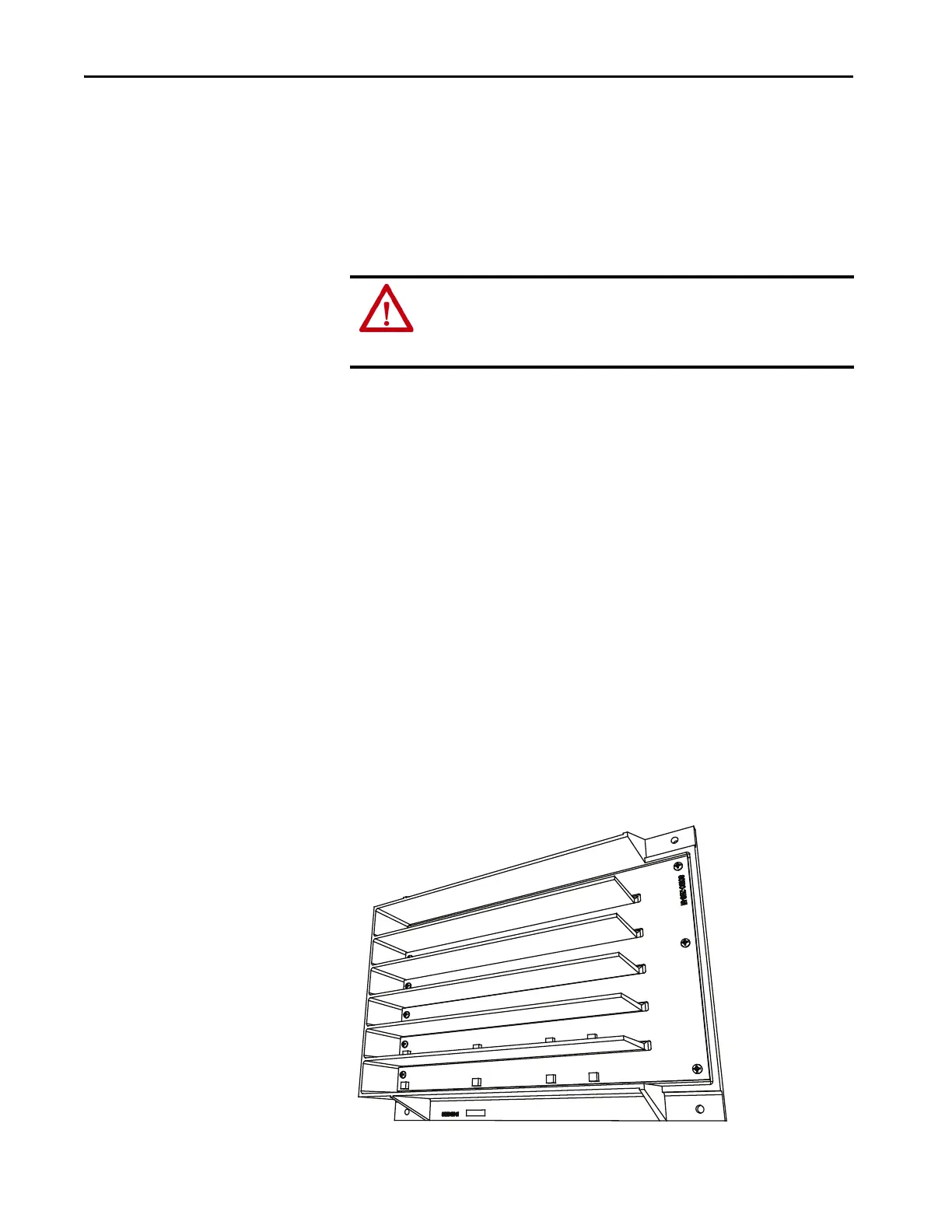
Figure 27 - Sensing Board with Mounting Hardware Placement
ATTENTION: To prevent electrical shock, disconnect the main power before
working on the sensing board. Verify that all circuits are voltage-free, using a
hot stick or appropriate high voltage-measuring device. Failure to do so may
result in injury or death.

 Loading...


