Rockwell Automation Publication 7000-UM202D-EN-P - May 2018 147
Control Component Definition and Maintenance Chapter 3
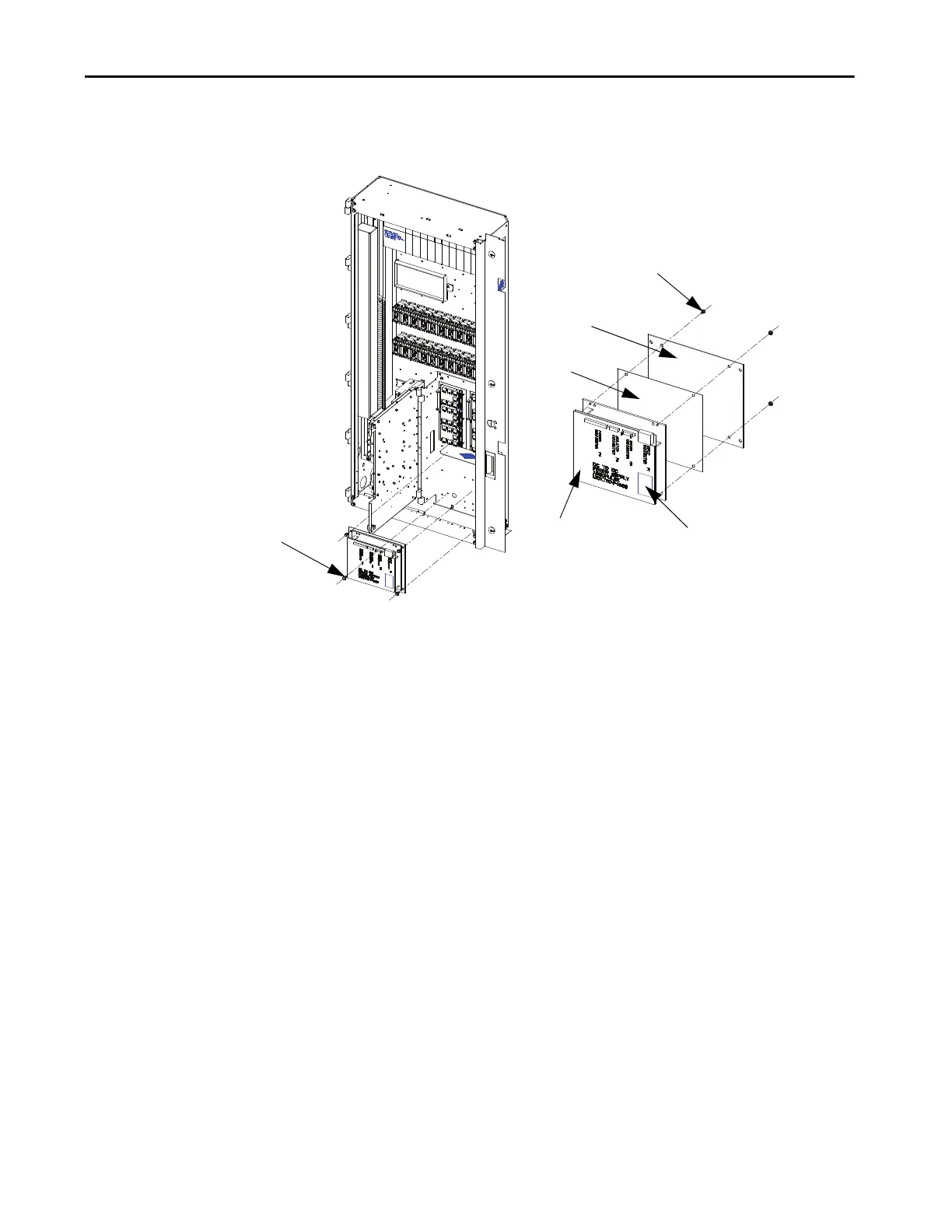
Replacing a DC/DC Power Supply
Figure 127 - Replacing a DC/DC Power Supply
1. With the drive energized, check that all output voltages are present
(view 1).
2. De-energize the drive, isolate and lock out the control power, and
remove all wire connections from the unit (view 1).
3. Remove four M6 (H.H.T.R.S.) so you can remove the DC/DC power
supply assembly from the low voltage panel (view 1).
4. Remove four M4 (P.H.M.S.) and nylon shoulder washers from the back
of the mounting plate (view 2).
5. Install the new DC/DC power supply. Ensure you replace the black
insulation between the DC/DC power supply and the mounting plate.
Repeat steps 4, 3, 2, 1 in this order to replace unit (view 2).
6. Reconnect the P4 plug ground wire to the ground by the M10 bolt.
Take the following precaution when replacing printed circuit boards.
• Disconnect all drive power.
• Leave the replacement board in the anti-static bag until needed.
• Use an anti-static wrist strap, grounded in the low voltage control
section.
There are no direct screw/terminal connections on any of the low voltage
circuit boards. All wire/terminal connections plug into the circuit boards. This
means that changing boards only requires the removal of the plugs, minimizing
the chance of mistakes when reconnecting all of the wiring.
M4 Hardware and Nylon
Shoulder Washer
Mounting Plate
Black
Insulation
Part ID Label
DC/DC Power
Supply
M6 Hex Head
Cap Screw

 Loading...


