168 Rockwell Automation Publication 7000-UM202D-EN-P - May 2018
Chapter 3 Control Component Definition and Maintenance
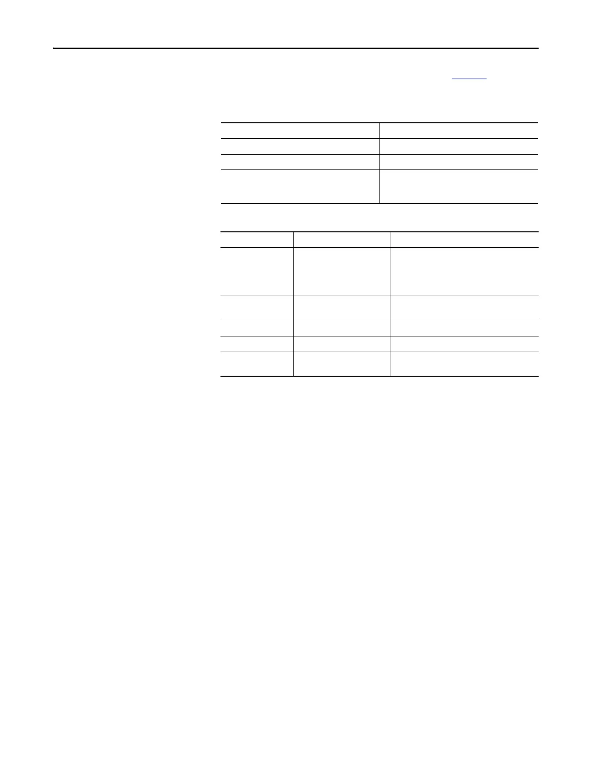
LED D1 and display U6 indicate the status of the board. Ta bl e 13 illustrates
the possible states for D1.
Replacing the External Input/Output Board
1. Disconnect and lock out all medium voltage and control voltage power
to the drive.
2. Mark the location and orientation of all the plugs, cables, and
connectors into the XIO board. Use the electrical drawing as a reference.
3. Ground your static strap, and disconnect all of the power connections.
4. Remove the XIO board assembly from the low voltage control cabinet.
The XIO board mounts on a DIN rail, so a special 3-piece assembly
secures the board. The assembly does not come with the new board, so
you must remove the old board from the assembly and install the new
board in its place.
5. Install the new XIO board assembly in the low voltage control cabinet.
6. Reconnect all connections and verify the locations.
7. Apply low voltage power and complete both system and medium voltage
tests to ensure the new board functions properly.
Table 13 - Color Status Explanation for LED D1
LED Status Description
Solid Green Normal operation
Solid Red Board failure
Alternate Flashing of Red and Green No communication available to ACB board (normal at
power on, during firmware download and with
unprogrammed drive)
Table 14 - Status of U6 Display
Display Description Explanation
— No valid address found – More than six XIO cards on network
– XIO cable failure
– XIO card failure
– ACB failure
0 Card in “Master” mode – Rockwell Automation use only
– Remove connection to J3 and recycle power
1 – 6 Valid address Normal
Decimal point ON Indicates network activity Normal
Decimal point OFF No activity on the network Normal at power on, during firmware download and
with unprogrammed drive

 Loading...


