156 Rockwell Automation Publication 7000-UM202D-EN-P - May 2018
Chapter 3 Control Component Definition and Maintenance
Status Indicators
There are two power status indicators on the ACB labeled D7 and D9:
• D9 is the ±15V DC voltage-OK signal
• D7 is the +5V DC voltage present signal.
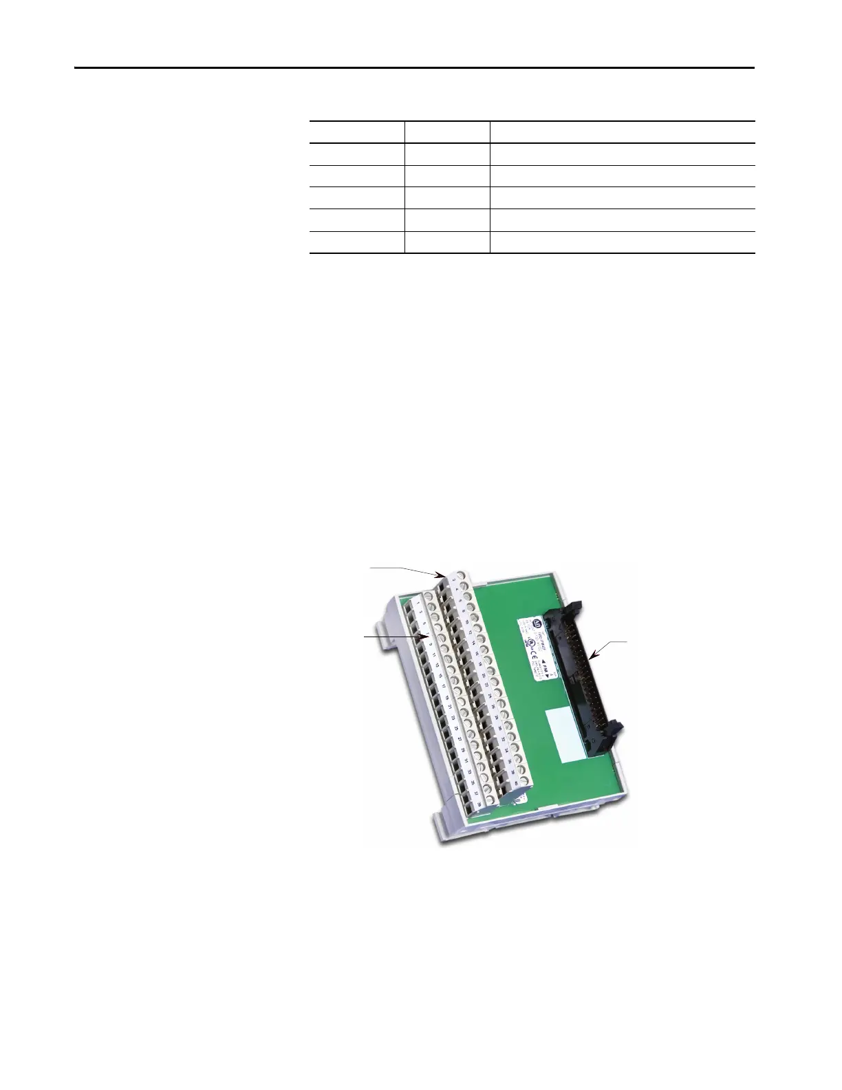
Interface Module (IFM)
The interface module makes all your connections to the ACB. The pin
numbers listed on the following pages refer to the IFM pin numbers.
Figure 131 - Interface Module (IFM)
ACB-TP79 OP Output contactor command
ACB-TP80 BPIS Bypass isolating switch
ACB-TP81 BPCS Bypass contactor status
ACB-TP82 BP Bypass contactor command
ACB-TP83 DGND Digital ground return
Table 10 - Test Points on Analog Control Board (Continued)
Test points Name Description
Even pin numbers
Odd pin numbers
Connection toACB (J8)

 Loading...


