82 Rockwell Automation Publication 7000-UM202D-EN-P - May 2018
Chapter 2 Power Component Definition and Maintenance
Replacing Sharing Resistors
Normally the sharing resistor is part of the snubber resistor assembly. Replacing
the sharing resistor requires also replacing the snubber resistor.
The sharing and snubber resistors are normally located on the backside of the
PowerCage module. See page 76
for removing and replacing snubber resistors.
Silicon Controlled Rectifier
PowerCage Modules
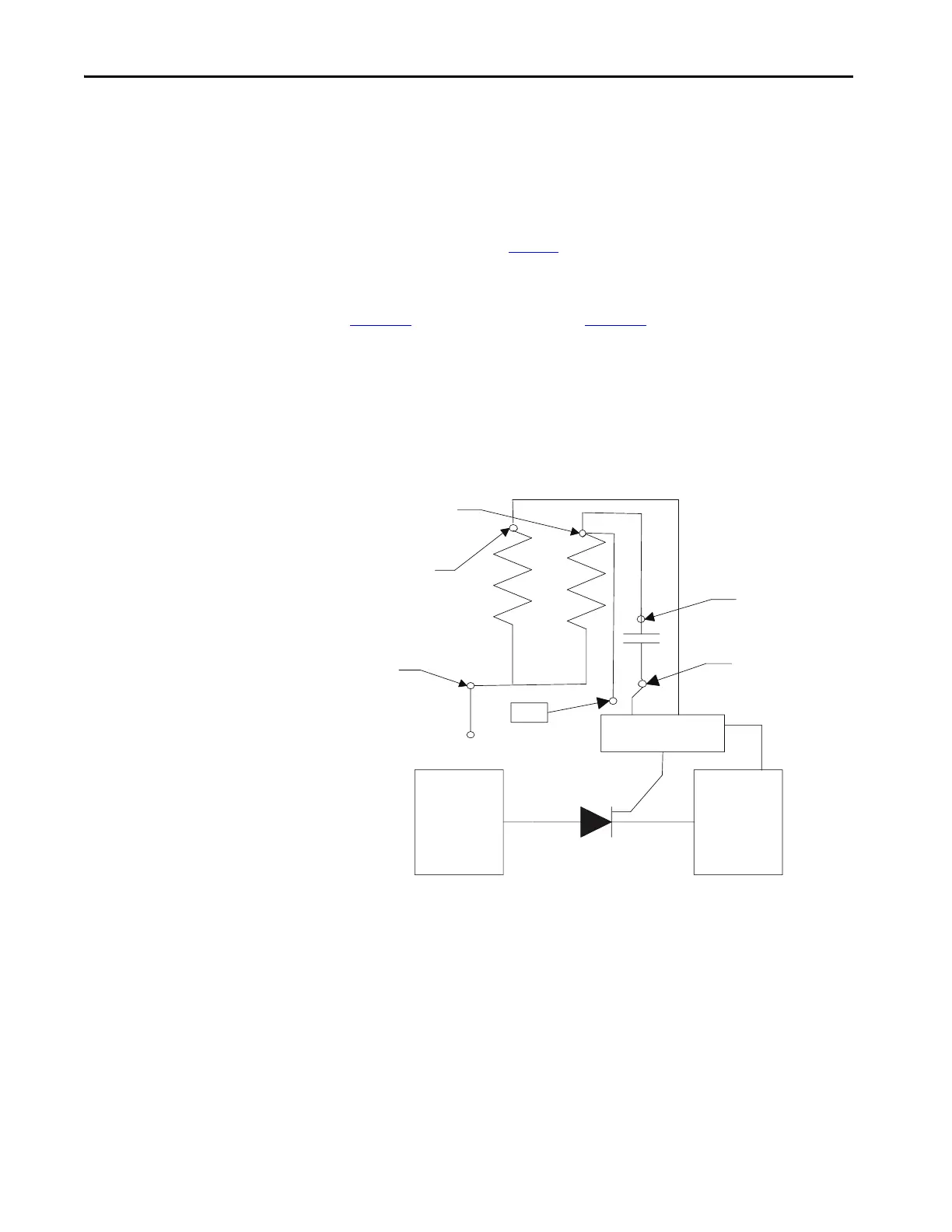
Figure 72 shows the snubber circuit. Figure 73 shows the physical locations of
the same circuit.
Disconnect the 2-pole plug to the gate driver board marked TB1 on the circuit
board. Measure the resistance from the point of the plug that connects to the
point labeled V.SENSE on the gate driver board to the anode side heatsink. A
value of 80 kΩ indicates a good sharing resistor.
Figure 72 - Snubber Circuit for SCR Rectifier Module
Rsn-2
Rsh
Rsn-1
TP
Anode
Cathode
SPGDB
Cs-1
Cs-2

 Loading...


