176 Rockwell Automation Publication 7000-UM202D-EN-P - May 2018
Appendix A Specifications
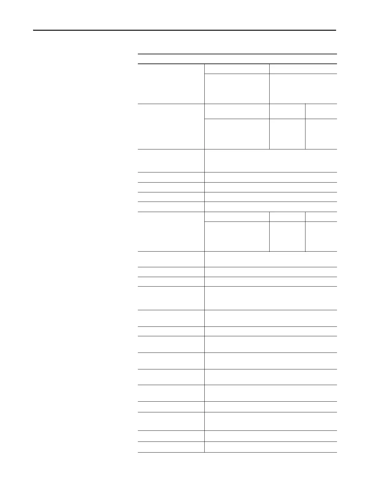
Number of Inverter SGCTs Voltage SGCTs (per phase)
2400V
3300V
4160V
6600V
2
4
4
6
Inverter PIV Rating
(Peak Inverse Voltage)
Voltage PIV (each
device)
Total PIV
2400V
3300V
4160V
6600V
6500V
6500V
6500V
6500V
6500V
13,000V
13,000V
19,500V
Rectifier Designs Direct-to-Drive™ (transformerless AFE rectifier)
AFE with separate isolation transformer
18-pulse with separate isolation transformer
Rectifier Switch SCR (18-pulse), SGCT (AFE Rectifier)
Rectifier Switch Failure Mode Non-rupture, Non-arc
Rectifier Switch Failure Rate (FIT) 50 (SGCT) 100 (SCR) per 1 Billion Hours Operation
Rectifier Switch Cooling Double Sided, Low Thermal Stress
Number of Rectifier Devices per
phase
Voltage AFE 18-pulse
2400V
3300V
4160V
6600V
2
4
4
6
6
6
6
6
Output Current Harmonics
(1
st
…49
th
)
< 5% (full load, full speed)
Output Waveform to Motor Sinusoidal Current / Voltage
Medium Voltage Isolation Fiber Optic
Modulation techniques SHE
Synchronous Trapezoidal PWM
Asynchronous or Synchronous SVM (Space Vector Modulation)
Control Method Digital Sensorless Direct Vector
Full Vector Control with Encoder Feedback (Optional)
Tuning Method Auto Tuning via Setup Wizard
Speed Regulator Bandwidth 1…10 rad/s with standard control
1…20 rad/s with HPTC (optional)
Torque Regulator Bandwidth 15…50 rad/s with standard control
80…100 rad/s with HPTC (optional)
Torque Accuracy with HPTC
(optional)
+/- 5%
Speed Regulation
0.1% without Encoder Feedback
0.01…0.02% with Encoder Feedback
Acceleration/Deceleration Range
Independent Accel/Decel – 4 x 30 s
Acceleration/Deceleration Ramp
Rates
4 x Independent Accel/Decel
S Ramp Rate
Independent Accel/Decel – 2 x 999 s
Critical Speed Avoidance
3 x Independent with Adjustable bandwidth
Table 17 - General Design Specifications (Continued)
Description

 Loading...


